Staple detecting mechanism of electric stapler

a technology of detecting mechanism and stapler, which is applied in the direction of stapling tools, manufacturing tools, nailing tools, etc., can solve the problems of not only the durability of the staple sensor, but also the detection accuracy, so as to improve durability and enhance detecting accuracy

Inactive Publication Date: 2006-05-23
MAX CO LTD
View PDF7 Cites 567 Cited by
  • Summary
  • Abstract
  • Description
  • Claims
  • Application Information

AI Technical Summary

Benefits of technology

[0015]According to the staple-detecting mechanism for the electric stapler of the present invention, which has been accomplished in view of the above problems, a mechanism for detecting a front edge of a staple sheet is made smaller with enhanced detecting accuracy and improved durability.
[0016]In order to solve the above problems, a staple sheet-detecting mechanism of an electric stapler as set forth in claim 1 relates to a staple sheet-detecting mechanism of an electric stapler, which detects whether a staple sheet is positioned in a feeding passage for the staple sheet when a forming plate which is adapted to form staples of the staple sheet in a one side-opened rectangular form and a driver which is adapted to penetrate the staple formed in the one side-opened rectangular shape into copy papers are arranged above a tip edge of the feeding passage in a feeding direction of the staple sheet while directed to a direction orthogonal to the feeding passage and are moved relative to said feeding passage, and the detecting mechanism is characterized in that a rocking member is arranged above the tip edge of said feed passage, one end of the rocking member being adapted to push the tip edge of the staple sheet in the feeding direction and the other end thereof being adapted to turn on or off a detecting element, a rocking fulcrum of the rocking member is located biased to a side of the feeding passage than a side of the detecting element, and the forming plate and the driver are formed with escape depressions, respectively, so as to avoid interference against the rocking member.

Problems solved by technology

Therefore, the other end of the staple sensor 13 does not move over a distance sufficient enough to switch a signal for a not shown photointerruptor opposed to the sensor with the result that an erroneous signal may be generated.
Consequently, there are problems that not only the detection accuracy but also the durability of the staple sensor 13 itself drop.

Method used


Image

  • Staple detecting mechanism of electric stapler
  • Staple detecting mechanism of electric stapler
  • Staple detecting mechanism of electric stapler

Examples


Embodiment Construction

[0035]In the following, one embodiment of the staple sheet-detecting mechanism of the electric stapler according to the present invention will be explained with reference to the drawings.

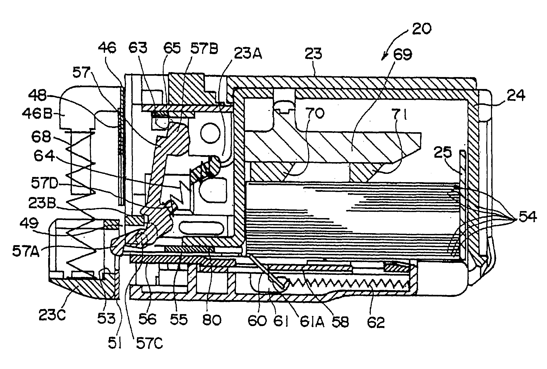
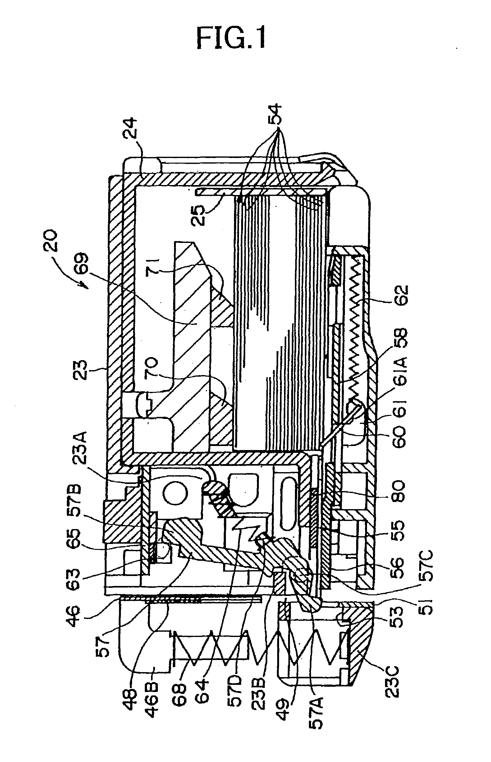
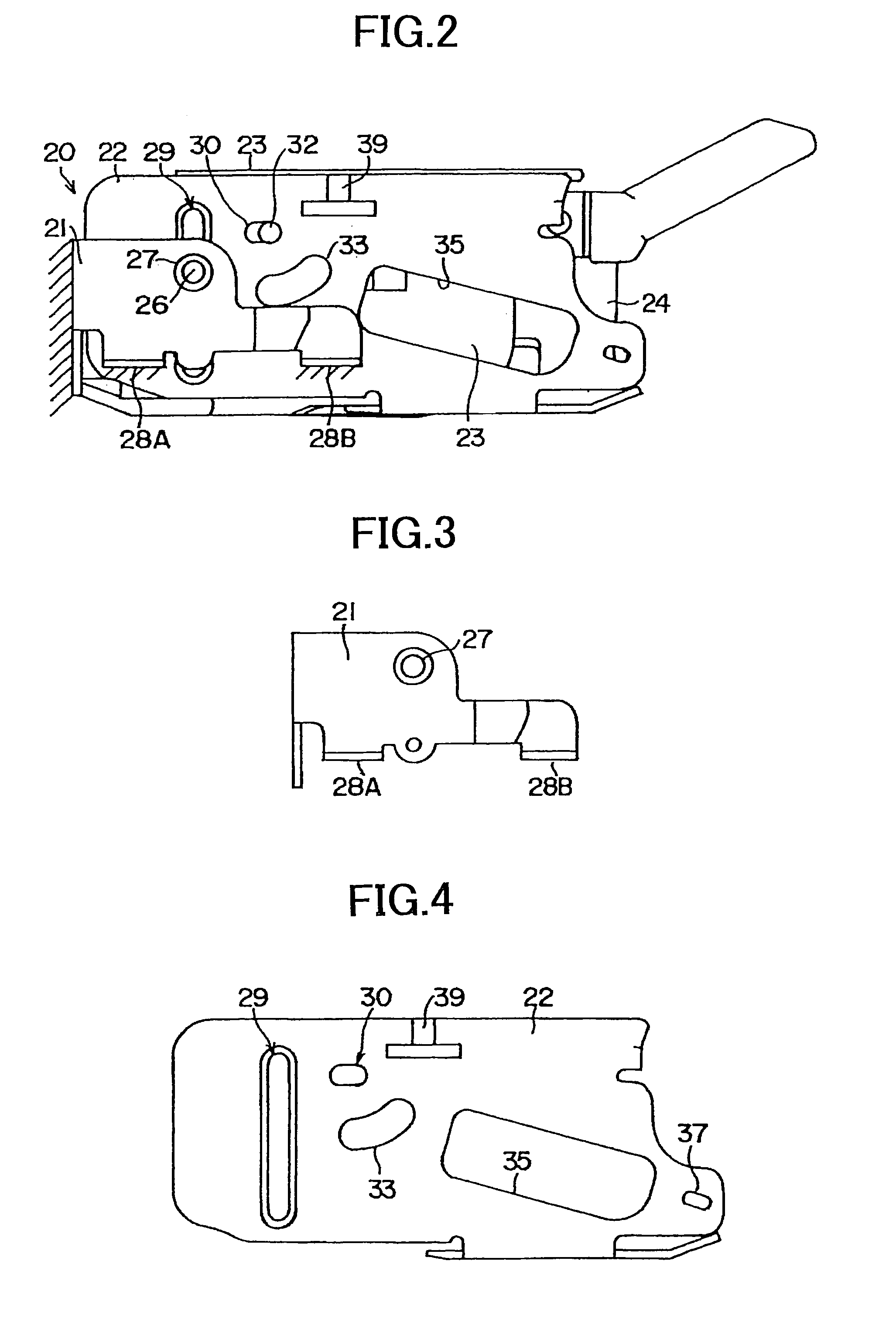
[0036]FIG. 2 shows an outlined construction of the electric stapler according to one embodiment. In FIG. 2, a reference numeral 20 shows an electric stapler. The electric stapler 20 comprises an outer casing 21 fixedly attached to a frame of a stacking mechanism of a copying machine, an inner casing 22 vertically movably supported by the outer casing 21, a magazine 23 swingably held in the inner casing 22, a cartridge casing 24 fitted into the magazine 23, and a cartridge 25 (See FIG. 1) received in the cartridge casing 24.

[0037]The outer casing 21 has a one side-opened rectangular planar shape to house the inner casing 22. As shown in FIGS. 3 and 9, a side plate of the outer casing 21 is provided with a fitting hole 27 for a guide pine 26. The outer casing 21 has projecting pieces 28A and 28B proje...


PUM

PropertyMeasurementUnit
distanceaaaaaaaaaa
shapeaaaaaaaaaa
timeaaaaaaaaaa

Abstract

A staple sheet-detecting mechanism of an electric stapler having improved detection accuracy and miniaturization has a passage for feeding a staple sheet composed of straight forward staples arranged in parallel, and a forming plate and driver arranged above an anvil of the passage. A staple is inserted into papers located under the staple by moving the forming plate and the driver to a side of the staple. Above the anvil, where the forming plate waits, is a sensor (rocking member) of which one end contacts a tip edge of the staple sheet in a feeding direction, while the other end turns on or off an interrupter (detecting element). A rocking fulcrum of the sensor is provided biased to a side of the staple sheet in the passage. The forming plate and the driver are provided with recessed portions and, respectively, for allowing the sensor to rock.

Description

TECHNICAL FIELD[0001]The present invention relates to a staple-detecting mechanism of an electric stapler. More particularly, the invention relates to a staple-detecting mechanism for detecting whether a staple sheet formed in a sheet-like shape is located at a forming position of a forming mechanism or not when a stapler is separated from the staple sheet and formed in a one side-open rectangular shape in binding copying papers.PRIOR ART[0002]Heretofore, there have been some stackers, etc. in copy machines and the like in which an electric stapler is arranged.[0003]FIG. 16 shows an outlined construction of such an electric stapler 1. In this electric stapler 1, staple sheets 3 (See FIG. 17) each constituted by arranging numerous straight forward staples in parallel and bonding them in a sheet-like shape with an adhesive are used.[0004]As shown in FIG. 16, the staple sheets 3 are stacked and stored in a cartridge 4. Every staple sheet 3 is fed from the cartridge 4 with a roller 5 su...

Claims


Application Information

Patent Timeline
Patent Type & Authority Patents(United States)
IPC IPC(8): B27F7/17B27F7/19B27F7/38
CPCB27F7/38B25C5/16
Inventor HARAMIISHI, KIICHI
Owner MAX CO LTD
Why Eureka
Try Eureka