Staple removal tool

a technology for removing staples and tools, which is applied in the field of tools for removing staples, can solve the problems of damage to the underlying frame, difficulty in physical insertion of tools, and damage to upholstery by tearing or puncturing, and achieves the effect of improving frictional conta

Inactive Publication Date: 2006-05-23
BUCH PAUL M +1
View PDF14 Cites 26 Cited by
  • Summary
  • Abstract
  • Description
  • Claims
  • Application Information

AI Technical Summary

Benefits of technology

[0007]In accordance with embodiments of the present invention, a staple removal tool is provided, the tool comprising a handle, working end, and a shaft interconnected between the handle and the working end. The working end includes a forked portion having a single substantially V-shaped slot positioned between two prongs. Either prong is adapted to be inserted under a staple that is to be removed. The working end has a first width at the tips of the prongs, widens to a maximum width creating a lever arm, and narrows back to the width of the shaft. In use, after a prong of the working end is inserted under a staple, the handle may be rotated causing the working end to roll on the lever arm resulting in the staple being pulled from the material. The working end may include a grooved surface providing enhanced frictional contact between the working end and the staple.
[0008]In accordance with another embodiment of the present invention, a staple removal tool is provided comprising a handle, working end, and a shaft interconnected between the handle and working end, the working end being operable to remove staples from corners and grooves. The working end preferably includes a grooved surface providing enhanced frictional contact between the working end and the staple. The working end includes a prong operable to be inserted between a staple and a furniture piece, the working end widening from the prong and thereafter narrowing in an arc to provide a rocker arm. In use, after the prong is inserted under a staple, the handle may be rotated causing the working end to roll on the rocker arm resulting in the staple being pulled from the material.

Problems solved by technology

This force may result in damage to the underlying frame as one end of the removal tool may scratch or dent the underlying frame.
Furthermore, the upholstery may also be damaged by tearing or puncturing.
Another difficulty with wedging a tool between the staple and the underlying frame is the physical insertion of the tool, which may be difficult due to the staple being in close contact with both the upholstery and the frame.
However, while these tools are designed to lift up the staple, they are not designed for easy insertion under the staple.
Furthermore, the prying motion associated with using the tools requires more movement on the part of the user and is more prone to breaking the staple in its middle, leaving two pieces, and also further increases the chance of damage to the frame and fabric.
Current staple pullers are too large to fit into tight areas and are prone to damaging the item if used.

Method used


Image

  • Staple removal tool
  • Staple removal tool
  • Staple removal tool

Examples


Embodiment Construction

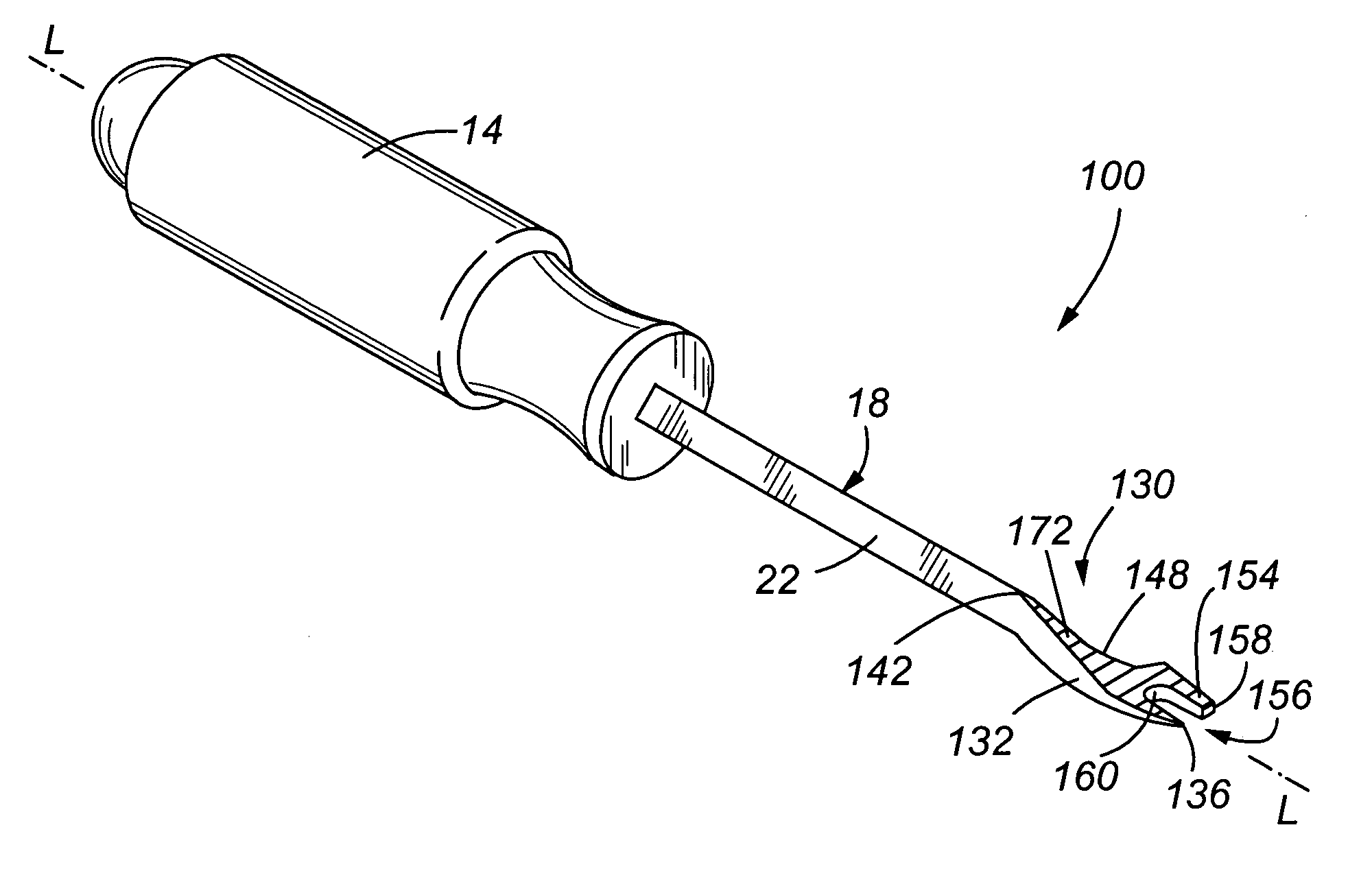
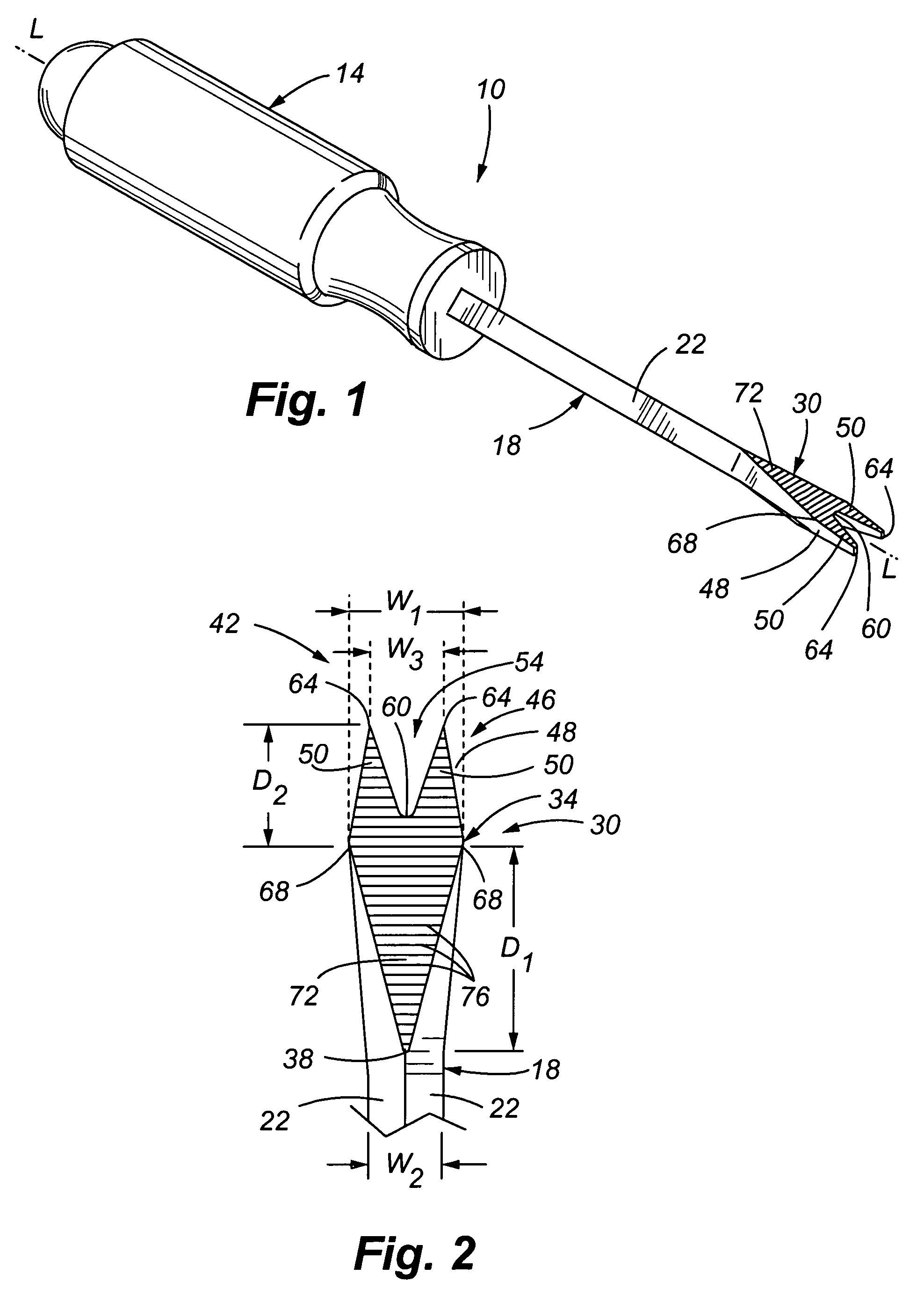
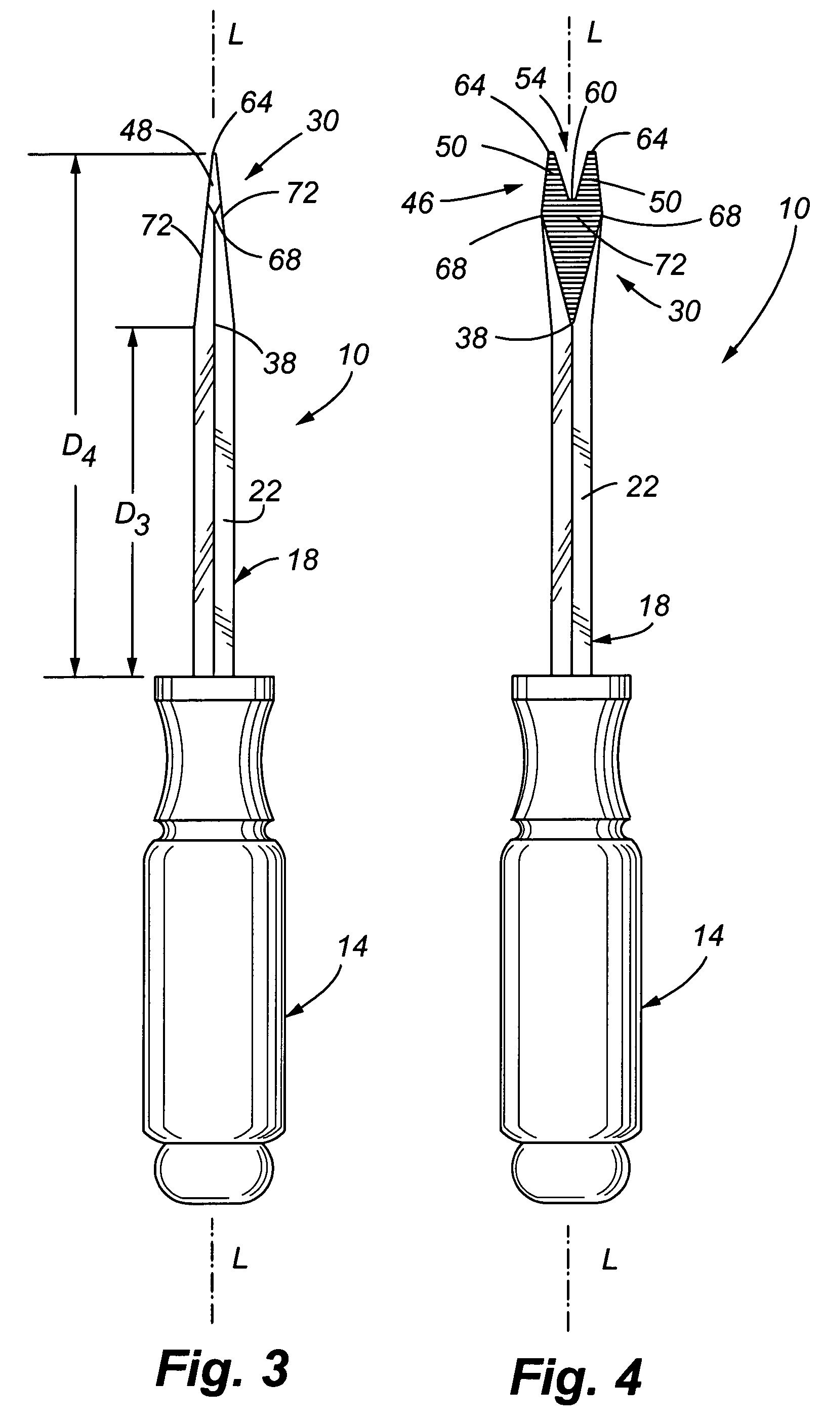
[0024]The present invention overcomes the previously described problems and meets the aforementioned needs. Referring now to FIG. 1, in accordance with embodiments of the present invention, a staple removal tool 10 is shown. The tool 10 includes a handle 14. The handle 14 is configured to comfortably accommodate a user's hand while using the tool 10, while also providing enough strength to withstand normal forces applied while removing staples. In one embodiment of the present invention, handle 14 is about 4.25 inches long, has a diameter of about 1.4 inches, and is formed of hexagonal plastic. Other configurations of the handle 14 may be employed, so long as a user may grasp the tool 10 in one hand with relative ease and comfort.

[0025]The tool 10 also includes a shaft 18 that is recessed or otherwise interconnected to handle 14. In one embodiment, the shaft 18 extends about 4 inches into the handle 14, and in another embodiment the shaft 18 extends about 2 inches into the handle 14...


PUM


Abstract

A staple removal tool includes a working end with an enlarged area and forked portion. The forked portion includes two prongs separated by a substantially V-shaped slot, wherein the V-shaped slot includes a rounded junction. The working end tapers in thickness along two non-parallel planar surfaces that may include grooves set transversely to the longitudinal axis of the tool. A second embodiment of the staple removal tool includes a working end with both outwardly and inwardly curved exterior surfaces. The outwardly curved exterior surface leads to a prong. A blunted tine is separated from the prong by a substantially U-shaped slot that includes a rounded junction. The working end tapers along two non-parallel planar surfaces that may include grooves set transversely to the longitudinal axis of the tool. Methods of using the tools are also provided.

Description

CROSS REFERENCE TO RELATED APPLICATION[0001]The present application claims the benefit of U.S. Provisional Application No. 60 / 538,659 filed on Jan. 23, 2004, the entire disclosure of which is incorporated herein by reference in its entirety.FIELD OF THE INVENTION[0002]The present invention is directed to tools for removing staples, and more specifically, to a hand tool for removing staples from a variety of items, including upholstery and shipping containers.BACKGROUND OF THE INVENTION[0003]A common undertaking in the furniture restoration business is the replacement, removal and repair of upholstery on various items. Such upholstery is commonly secured in-place using staples, tacks, or other devices, which hold the upholstery to the underlying frame. While reference will generally be made herein to staples, it will be understood that the invention applies broadly to cover all securement devices, including staples and tacks. Accordingly, when the upholstery is to be replaced, remove...

Claims


Application Information

Patent Timeline
Patent Type & Authority Patents(United States)
IPC IPC(8): B25C11/00
CPCB25C11/00
Inventor BUCH, PAUL M.HILL, SCOTTY W.
Owner BUCH PAUL M
Why Eureka
Try Eureka