Handle apparatus and cleaning device comprising same

a technology of cleaning device and handle, which is applied in the direction of metal-working hand tools, carpet cleaners, brushes, etc., can solve the problems of affecting the use of the handle interface of many current liquid dispensing or spray mops, damage to the trigger, and stress on the hand muscles of users, so as to reduce the likelihood of sliding against a wall and falling

Active Publication Date: 2016-07-14
NEXSTEP COMMERCIAL PROD LLC
View PDF11 Cites 10 Cited by
  • Summary
  • Abstract
  • Description
  • Claims
  • Application Information

AI Technical Summary

Benefits of technology

[0005]An object of the present invention is to provide a multi-functional handle apparatus for use on a cleaning instrument, such as a mop. Another object of the invention is to provide a handle apparatus that reduces the likelihood of sliding against a wall and falling to the floor. Yet another object of the invention is to provide a handle apparatus that includes a trigger and means for protecting the trigger in the event the apparatus falls to the floor. These and other objects of the invention can be achieved in various embodiments of the invention described below.
[0007]According to another embodiment of the invention, a gripping band is positioned on the outer surface of the oblate spheroid section. The gripping band facilitates frictional engagement with a wall surface when the handle apparatus is leaned against the wall.
[0016]According to another embodiment of the invention, the bulbous top section has a gripping band on its outer surface that is comprised of a material having a high coefficient of friction that facilitates frictional engagement with a wall surface.
[0019]According to another embodiment of the invention, the handle includes a trigger attached to the substantially cylindrical elongate section and extending outwardly therefrom, and a flange formed proximate the bottom end and extending outwardly from the substantially cylindrical elongate section a greater distance than the trigger. As such, the flange prevents the trigger from contacting a floor when the cleaning apparatus falls to the floor.
[0023]According to another embodiment of the invention, the handle includes a gripping band on the outer surface of the oblate spheroid section and extending around a circumference of the oblate spheroid section. The gripping band facilitates frictional engagement with a wall surface when the handle is leaned against the wall surface.

Problems solved by technology

The trigger and handle interface on many current liquid dispensing or spray mops are uncomfortable to use, and designed to be merely the triggers for the spray mop.
These triggers are typically designed to be operated in only one hand position, and to be activated with only two fingers at any one time, which causes stress on the user's hand muscles.
A frequent problem with liquid dispensing / spray mops, which are not used with a bucket, is that when a user attempts to lean the mop handle against a wall in a resting position, the handle will often slide against the wall and fall onto the floor, frequently resulting in damage to the trigger.
Current spray mops having a straight handle without grips can cause the user to grip the mop tightly when mopping and hold the wrist at an odd angle, leading to fatigue and injury.

Method used


Image

  • Handle apparatus and cleaning device comprising same
  • Handle apparatus and cleaning device comprising same
  • Handle apparatus and cleaning device comprising same

Examples


Embodiment Construction

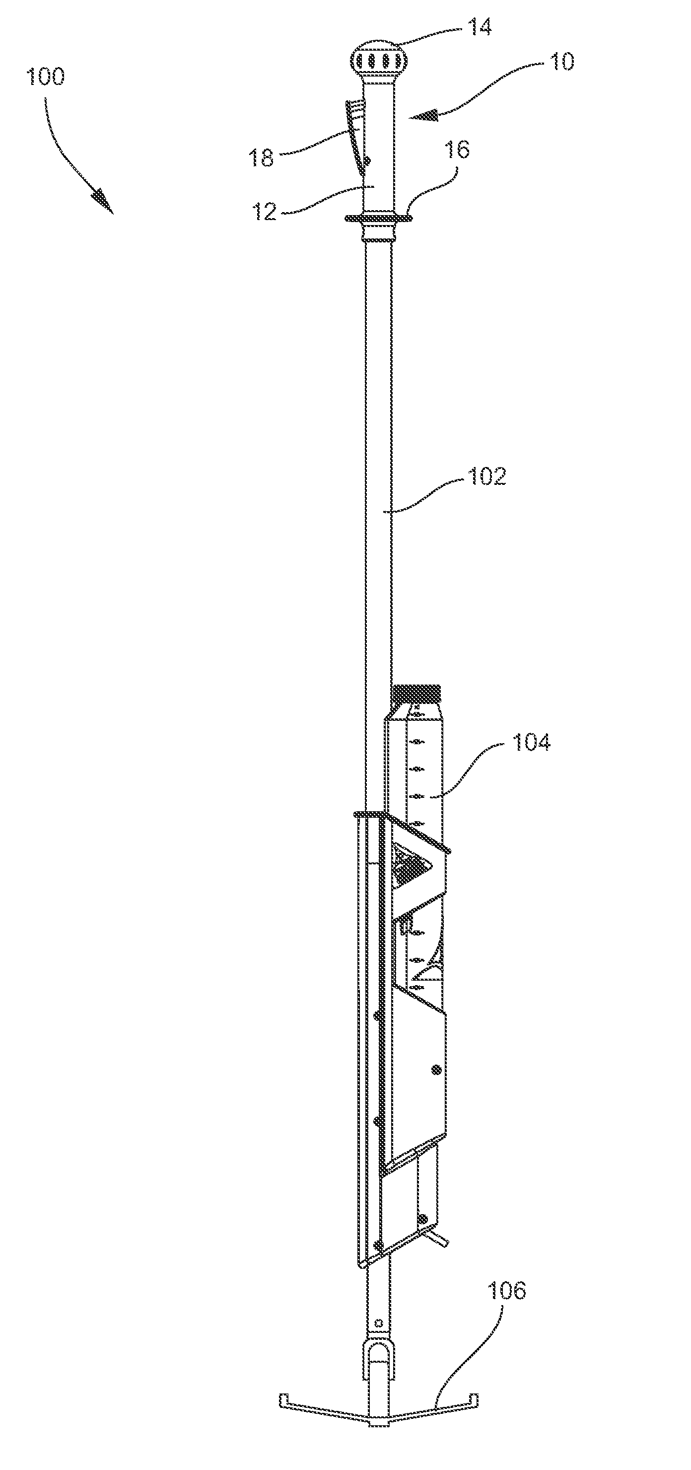
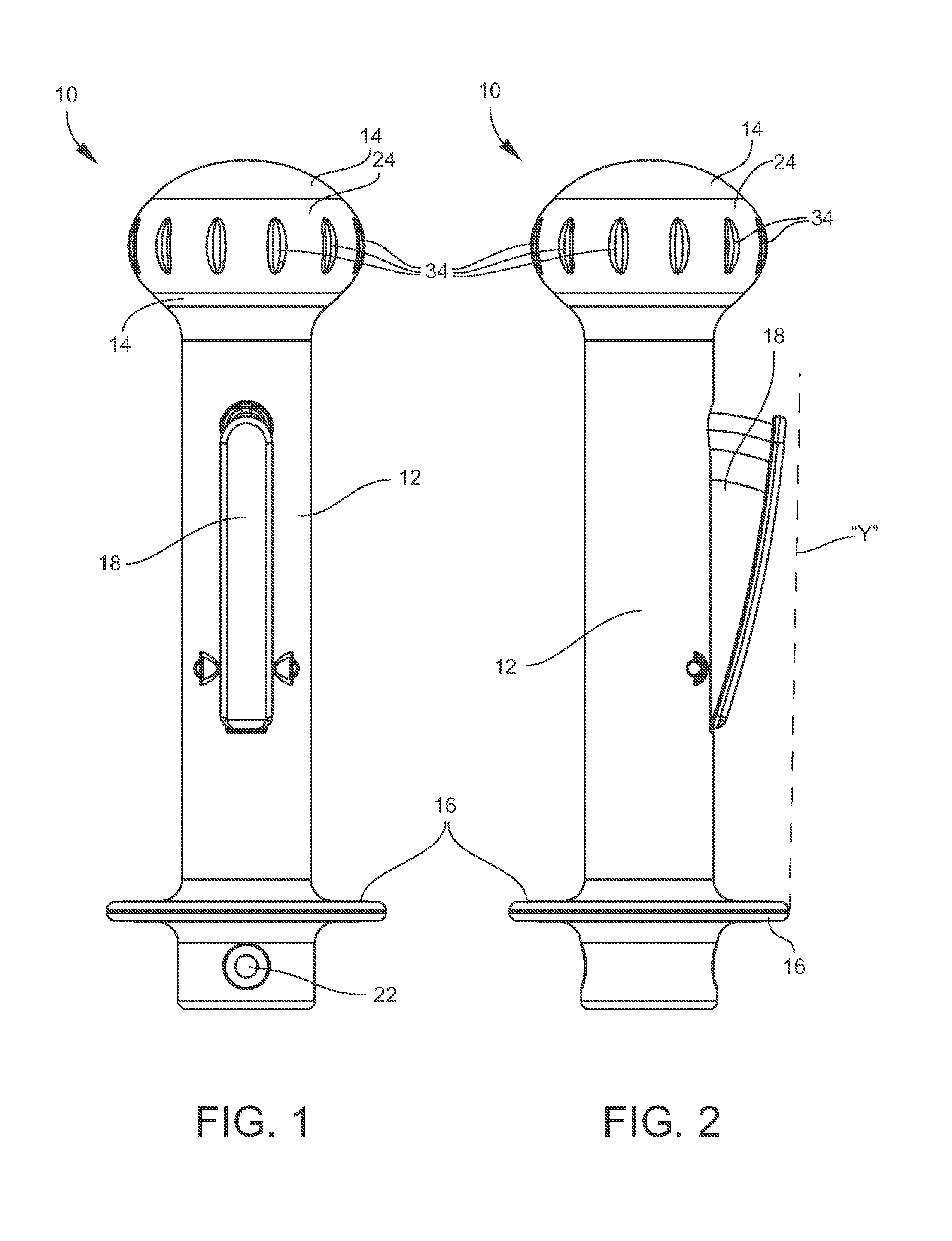
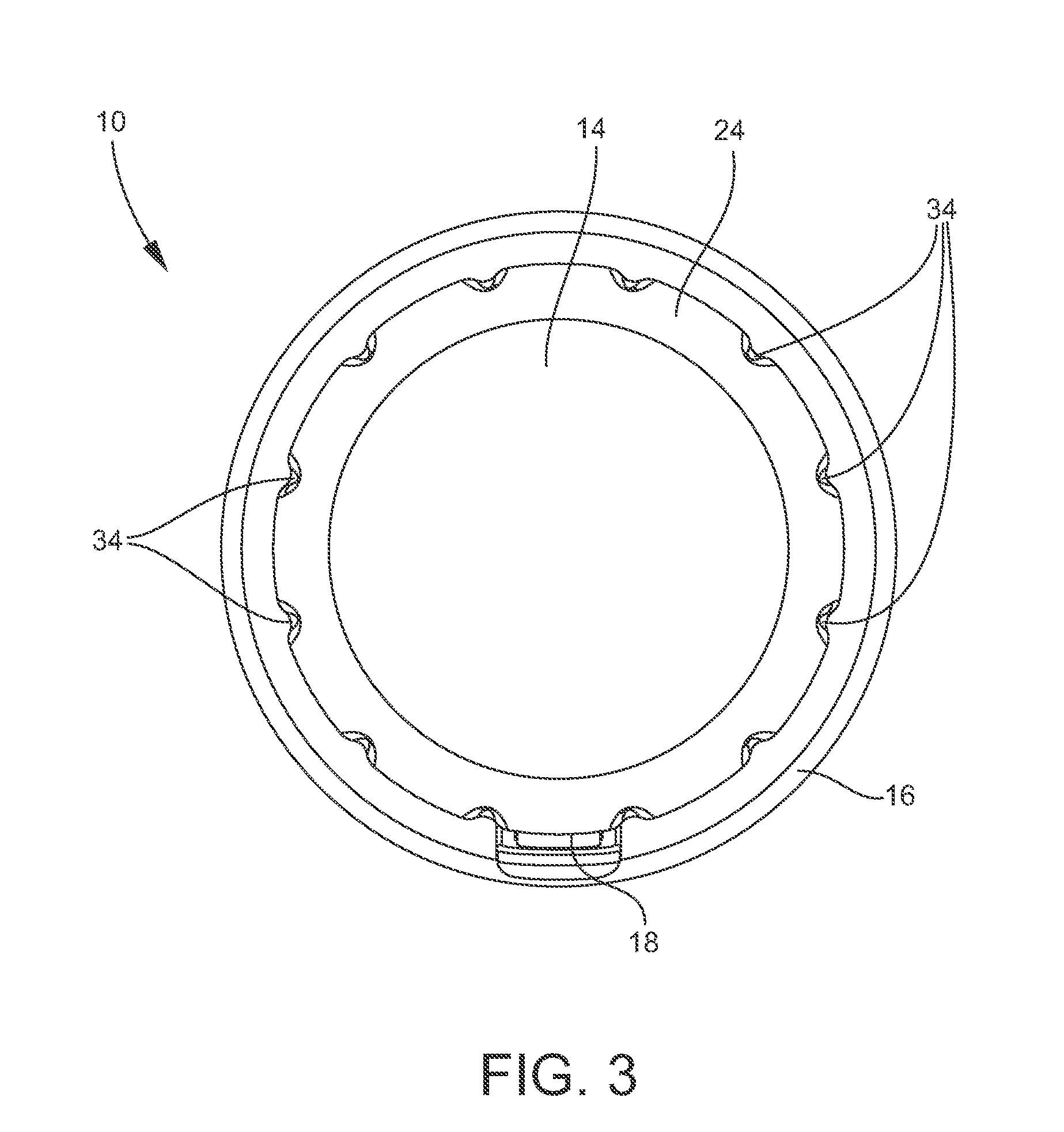
[0036]A handle apparatus according to a preferred embodiment of the invention is illustrated in FIGS. 1-3, and shown generally at reference numeral 10. As shown in FIGS. 1 and 2, the apparatus 10 comprises an elongate cylindrical shaft section 12, a bulbous section 14 formed at the top of the elongate cylindrical section 12, a flange section 16 formed proximate the bottom of the cylindrical section 12. A trigger 18 is positioned within a recess formed in the elongate cylindrical section 12, as shown in FIGS. 1 and 2. The handle 10 can generally be made of plastic or other suitable material. The handle 10 can be made by injection molding or other suitable process.

[0037]The handle apparatus 10 can be utilized on a cleaning implement, such as a liquid dispensing mop. A liquid dispensing mop according to a preferred embodiment of the invention is illustrated in FIGS. 4 and 5, and shown generally at reference numeral 100. The handle apparatus 10 is mounted at the top of an elongate shaft...


PUM


Abstract

A handle apparatus includes a substantially elongate cylindrical section, a bulbous top section formed at the top of the elongate cylindrical section, and a flange section formed proximate the bottom of the cylindrical section. A trigger can be positioned within a recess formed in the elongate cylindrical section. The flange can extend outwardly from the elongate cylindrical section a greater distance than the trigger to prevent damage to the trigger if the handle falls to the ground. The bulbous section can have an oblate spheroid shape, and a gripping band that provides a comfortable grip to the user and helps prevent the handle from slipping when leaned against a wall. The handle can be utilized on a cleaning implement, such as a liquid dispensing mop.

Description

CROSS REFERENCE TO RELATED APPLICATIONS[0001]This application claims priority to U.S. Provisional Patent Application No. 62 / 102,648, filed Jan. 13, 2015, and which is incorporated herein.TECHNICAL FIELD OF INVENTION[0002]The present invention relates to a handle apparatus that can be used on cleaning implements and the like. One embodiment of the invention comprises a multi-function one piece top grip and trigger apparatus for a liquid dispensing or spray mop.BACKGROUND OF INVENTION[0003]The trigger and handle interface on many current liquid dispensing or spray mops are uncomfortable to use, and designed to be merely the triggers for the spray mop. These triggers are typically designed to be operated in only one hand position, and to be activated with only two fingers at any one time, which causes stress on the user's hand muscles. A frequent problem with liquid dispensing / spray mops, which are not used with a bucket, is that when a user attempts to lean the mop handle against a ...

Claims


Application Information

Patent Timeline
Patent Type & Authority Applications(United States)
IPC IPC(8): A47L13/42
CPCA47L13/42A47L13/22
Inventor HOYLE, MARK ALLEN
Owner NEXSTEP COMMERCIAL PROD LLC
Why Eureka
Try Eureka