Electrical connector

a technology of electrical connectors and connectors, which is applied in the direction of coupling devices, connections, electrical apparatus, etc., can solve the problems of shrink rings not being installed to overlie a sheath and nipple, restricted cross sectional shape of the nipple, and insecure attachment of the sheath

Active Publication Date: 2005-07-19
ISODYNE
View PDF20 Cites 10 Cited by
  • Summary
  • Abstract
  • Description
  • Claims
  • Application Information

AI Technical Summary

Benefits of technology

[0013]Upon application of a rearward pulling force to the sheath, the sheath tends to bind between the rearward wall of the “C” band receiving channel and the rearward edges of the first and second steel “C” bands, effectively frictionally securing the sheath upon the nipple.

Problems solved by technology

A drawback or deficiency of such constant force spring adapter and sheathing assemblies is that the cross sectional shape of the nipple is restricted to circular.
Where the nipple has, for example, a non-circular oval square or rectangular shape, a circular constant force spring wrapped thereabout will undesirably press the sheathing into the outwardly opening channel only at discreet contact points, as opposed to continuous annular compression, resulting in an insecure attachment of the sheath.
A drawback or deficiency of shrink ring adapters it that shrink rings cannot be installed to overlie a sheath and nipple without extending such ring over the length of the sheathed cable or over the adapter.
Often, such extension of a heat shrink ring is mechanically blocked by cable or backshell structures.
A drawback or deficiency of such shrink ring adapter assemblies relates to the dimensions of the channel defining annular walls which outwardly extend from the nipple.

Method used


Image

  • Electrical connector
  • Electrical connector
  • Electrical connector

Examples


Embodiment Construction

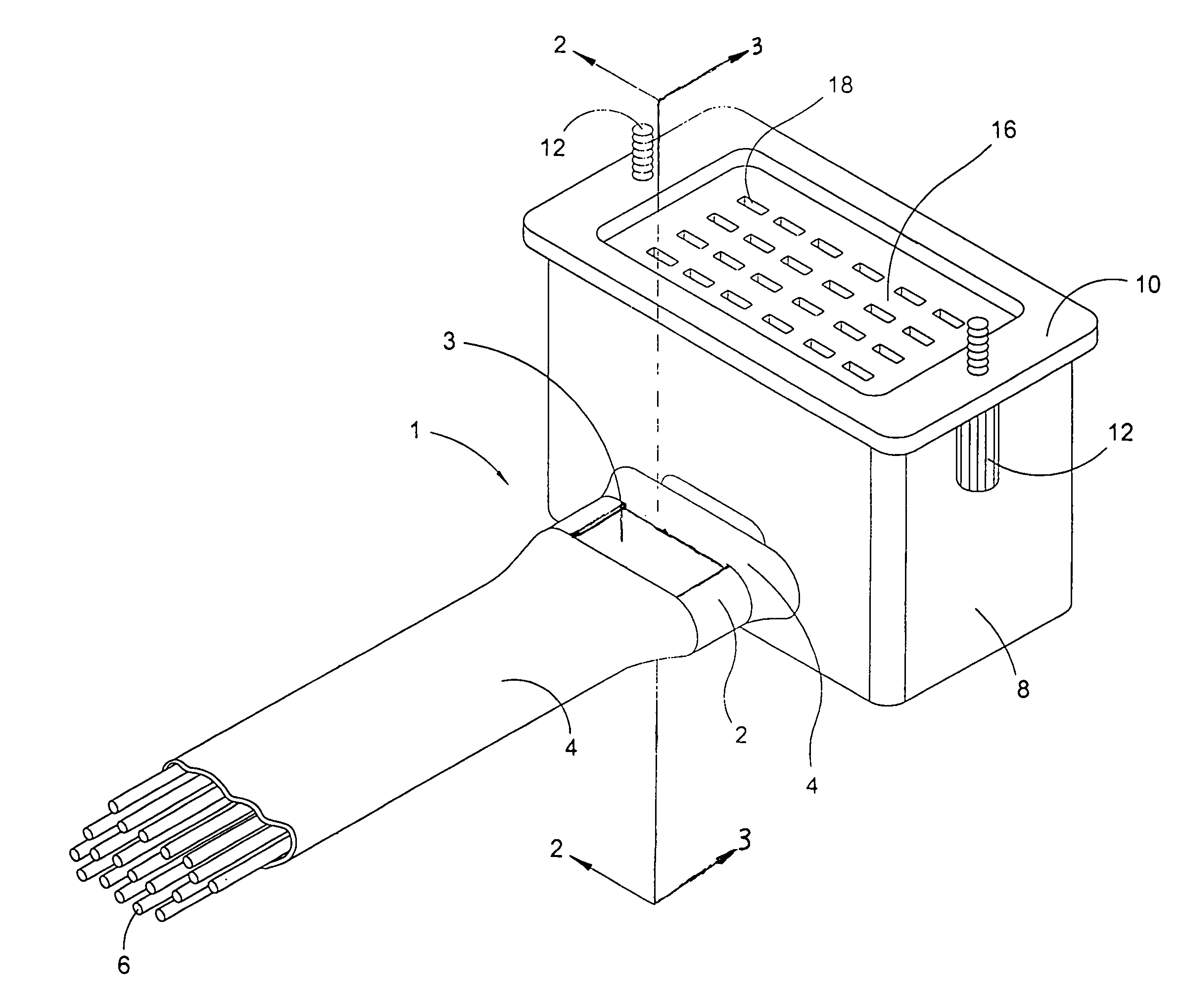
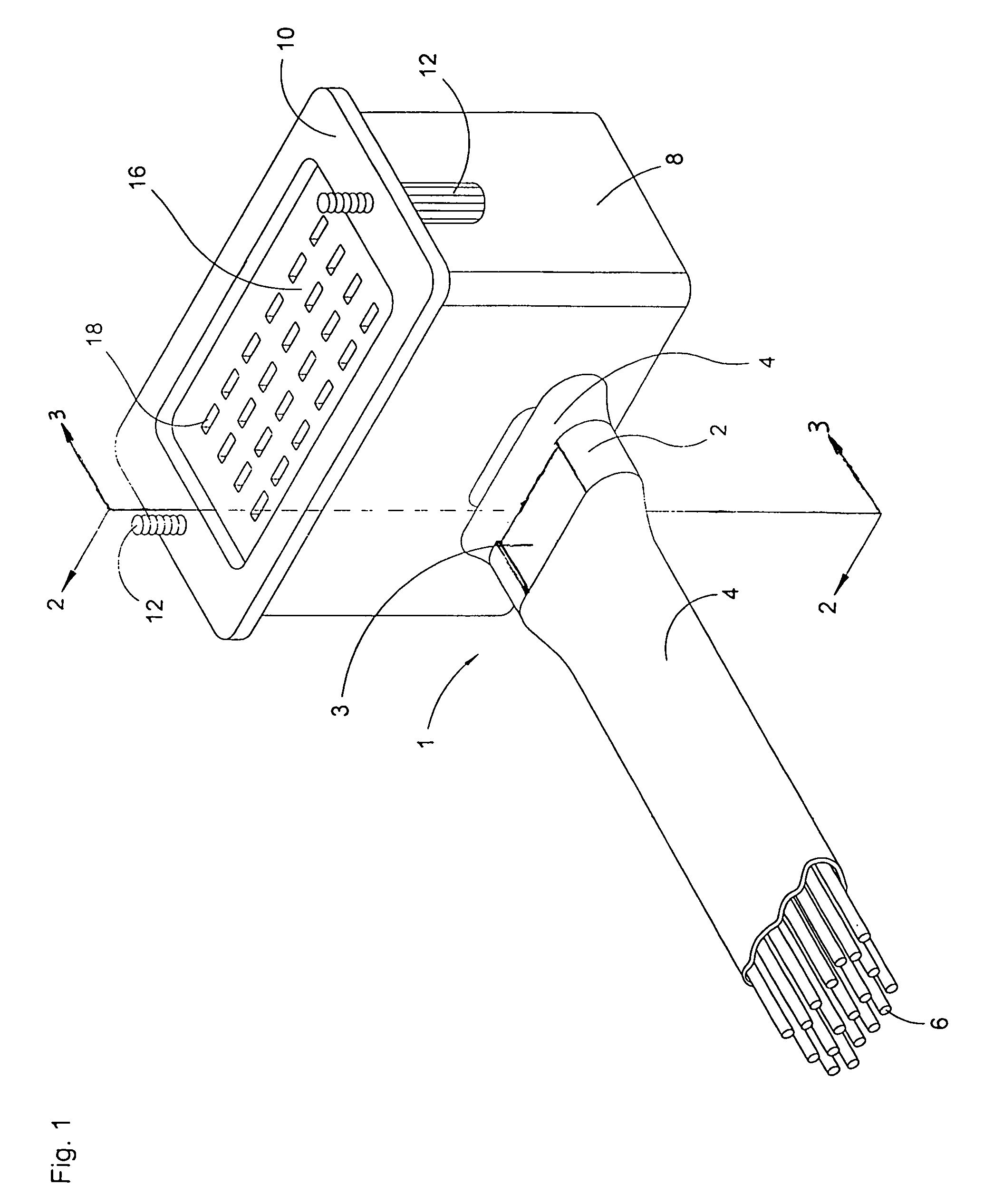
[0020]Referring now to the drawings, and in particular to FIG. 1, the instant inventive electrical connector is referred to generally by Reference Arrow 1. The electrical connector 1 comprises a hollow bored adapter housing 8, such housing having an outwardly extending mounting flange 10 supporting mounting screws 12.

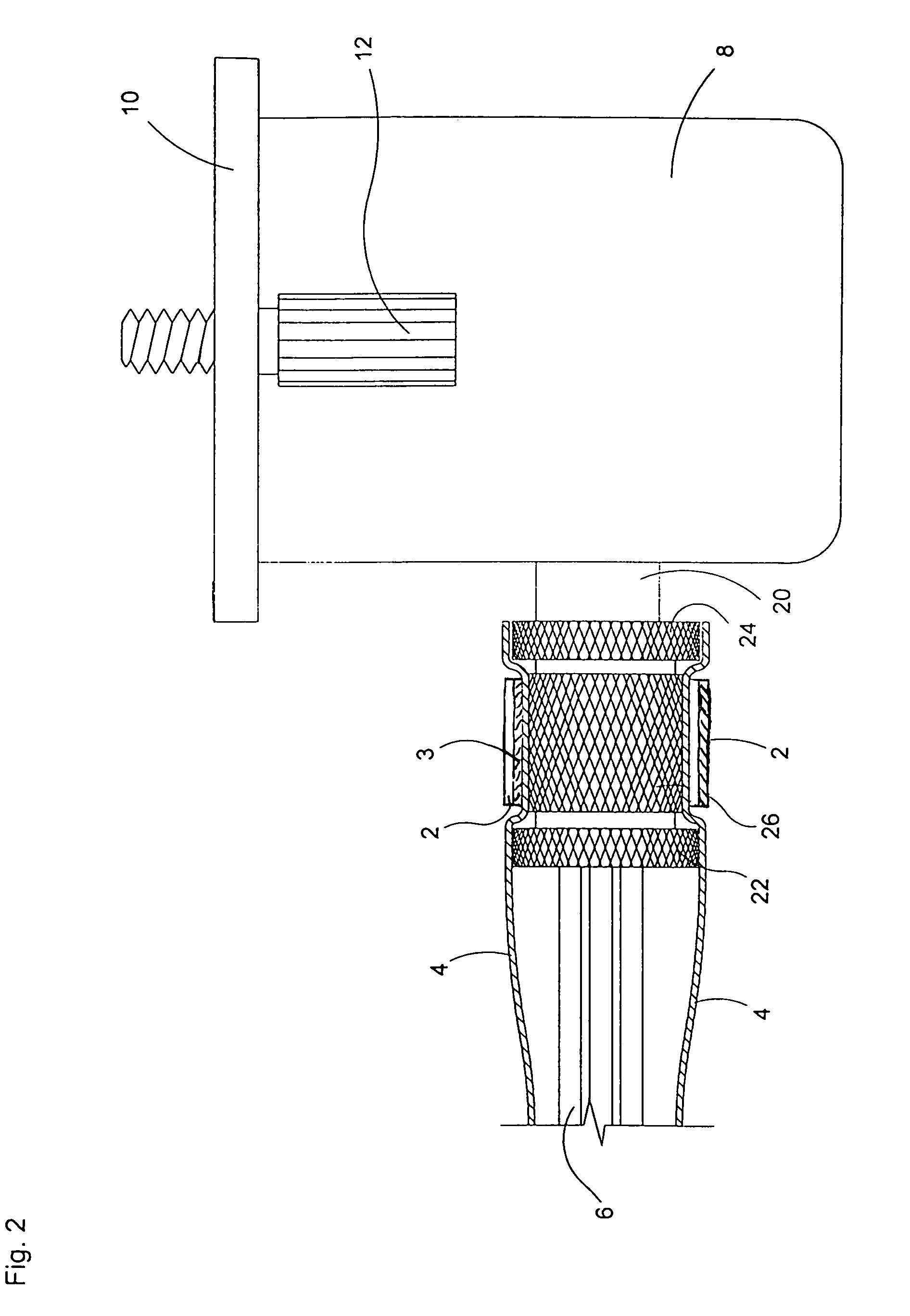
[0021]Referring simultaneously to FIGS. 1 and 2, a hollow bored nipple 20 extends rearwardly from the housing 8. A bundle of electrical cables 6 extends forwardly through, referring further to FIG. 3, the hollow bore 23 of nipple 20, and thence through the interior of housing 8 for fixed electrical contacts with electrical terminals 18 at terminal plate 16.

[0022]Referring simultaneously to all figures, walls 22 and 24 extend radially outward from nipple 20, such walls defining a “C” band receiving channel 26. Preferably, the floor of the “C” band receiving channel 26 is knurled. Also preferably, the outer surfaces of walls 22 and 24 are knurled.

[0023]A protective flexib...


PUM


Abstract

An electrical connector including an adapter, having an electric component attachment flange and a hollow bored nipple which is continuous with the adapter, the nipple having an outwardly opening “C” band receiving channel; an electrical cable extending through the nipple; a tubular sheath having a forward end overlying the hollow bored nipple's outwardly opening “C” band receiving channel; a first steel “C” band overlying the flexible tubular sheath, the first steel “C” band being positioned along the flexible tubular sheath so that it further overlies the outwardly opening “C” band receiving channel, the first steel “C” band extending the flexible tubular sheath into the outwardly opening “C” band receiving channel; and at least a second steel “C” band oppositely overlying the first steel “C” band.

Description

FIELD OF THE INVENTION[0001]This invention relates to electrical connection or coupling devices or assemblies comprising electric cables, a protective flexible sheathing or tubular armoring sleeve, and a cable terminating adapter shell.BACKGROUND OF THE INVENTION[0002]Constant force spring electrical connection adapter assemblies are known. Such assemblies typically comprise a hollow bored adapter shell for cable termination. Such adapter shells typically comprise a body portion having forward and rearward ends, the forward end of the body portion being adapted for removable attachment to an electrical component housing or to an electric junction box, and the rearward end of the body portion being adapted for removable attachment to a protective cable sheathing. Such forward adaptation typically comprises a helically threaded rotatable coupling nut or an outwardly extending mounting flange having mounting screw receiving apertures or slots. The rearward adaptation of such hollow bor...

Claims


Application Information

Patent Timeline
Patent Type & Authority Patents(United States)
IPC IPC(8): H01R13/58H01R13/621H01R9/03
CPCH01R13/5804H01R9/03H01R13/6215
Inventor REILLY, JOSEPH M.
Owner ISODYNE
Why Eureka
Try Eureka