Scalable high-performance bouncing apparatus

a high-performance, bouncing apparatus technology, applied in the direction of resilient force resistors, amusements, clutches, etc., can solve the problems of high performance, energy storage and return in the kilojoule range, unappealing, hazardous,

Inactive Publication Date: 2005-04-07
FLYBAR
View PDF36 Cites 11 Cited by
  • Summary
  • Abstract
  • Description
  • Claims
  • Application Information

AI Technical Summary

Benefits of technology

[0033] In accordance with yet another embodiment of the present invention, a bouncing system is provided. The bouncing system comprises a carriage assembly, a foot, a piston, a plurality of tension elements and a tool. The carriage assembly can support a user, and includes an exterior shell. The exterior shell defines an interior chamber and includes an aperture for access to the chamber. The foot is operable to extend away from and retract toward the carriage assembly. The piston connects the foot and the carriage assembly. At least a portion of the piston is within the interior chamber. The plurality of tension elements are in operative contact with the piston, and are contained within the interior chamber. At least some of the plurality of tension elements are individually mountable in an operative state and demountable in an inoperative state with respect to the piston. When a first tension element of the plurality is demounted, the first tension element is stored within the interior chamber. The tool is for mounting and demounting at least some of the plurality of tension elements. The tool includes a handle and an operative portion remote from the handle. The operative portion is capable of being passed through the aperture to effect mounting and demounting.

Problems solved by technology

High performance (that is, energy storage and return in the kilojoule range) is problematic for steel spring devices because the storage capacity of the material is low: about 80 joules / kilogram.
An apparatus of such weight would be unwieldy, unappealing and hazardous due to its own momentum.
Manufacturers have stopped at about one-third of this level (which still makes for a rather heavy apparatus).
Their attained height is 18 inches; they express disappointment, and blame the unwieldiness of the design.
All of these designs are limited by the modest capacity of their steel springs.
Such devices are successful as children's novelties but are not well-suited to more demanding applications due to the bulk of the entrapped air column.
There is, however, a practical problem: the energy stored is present in the form of heat at the bottom of the stroke—and due to the relatively large amount of energy and relatively small amount of gas, temperatures of several hundreds of degrees are attained.
A leading manufacturer has told me of experiments which ended in dismay when the cylinder became hot enough to burn the jumpers' legs.
These bundles would have made the upper mount about three inches wide—and this unshielded object would rake up and down between the knees and thighs of the jumper on each stroke; if the rider attempted to ride bowlegged to avoid it, his contact with and ability to control the stick (as well as his concentration) would suffer.
His mechanical design (which is for jumping stilts), however, is extraordinarily unsafe.
In the past, it has been difficult to perform adjustments on bouncing apparatuses.
While this system may permit the BowGo to be used on a lawn, it does little to accommodate uneven ground or tilting of the pogo, and does not distribute the load uniformly over the surface of the disk.
Thus, it has little capacity to transmit torque, and will not enable aggressive yaw maneuvers such as, e.g., aerial spins.
Unfortunately, an overstretched or relaxed spring / tension element may result in a loss of clearance between disengaged elements and the mounts that are used when the elements are engaged and operational.
Furthermore, such improperly tensioned components may cause hazardous conditions during operation of the apparatus.
Another issue concerning the spring / tension element occurs when a cap or end piece is attached to it.
Over time, the connection between the spring / tension element and the cap / end piece may fail.
This may cause a hazardous condition, and may also require repairs or replacements, which add unwanted costs.

Method used


Image

  • Scalable high-performance bouncing apparatus
  • Scalable high-performance bouncing apparatus
  • Scalable high-performance bouncing apparatus

Examples


Embodiment Construction

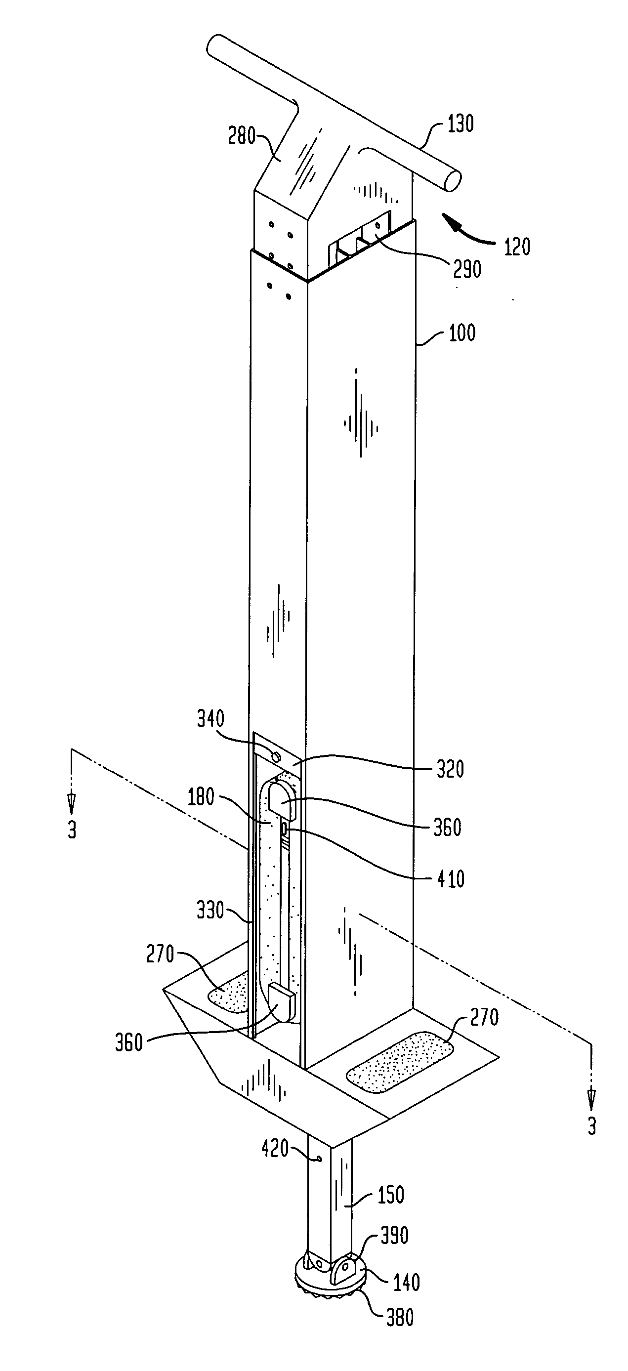
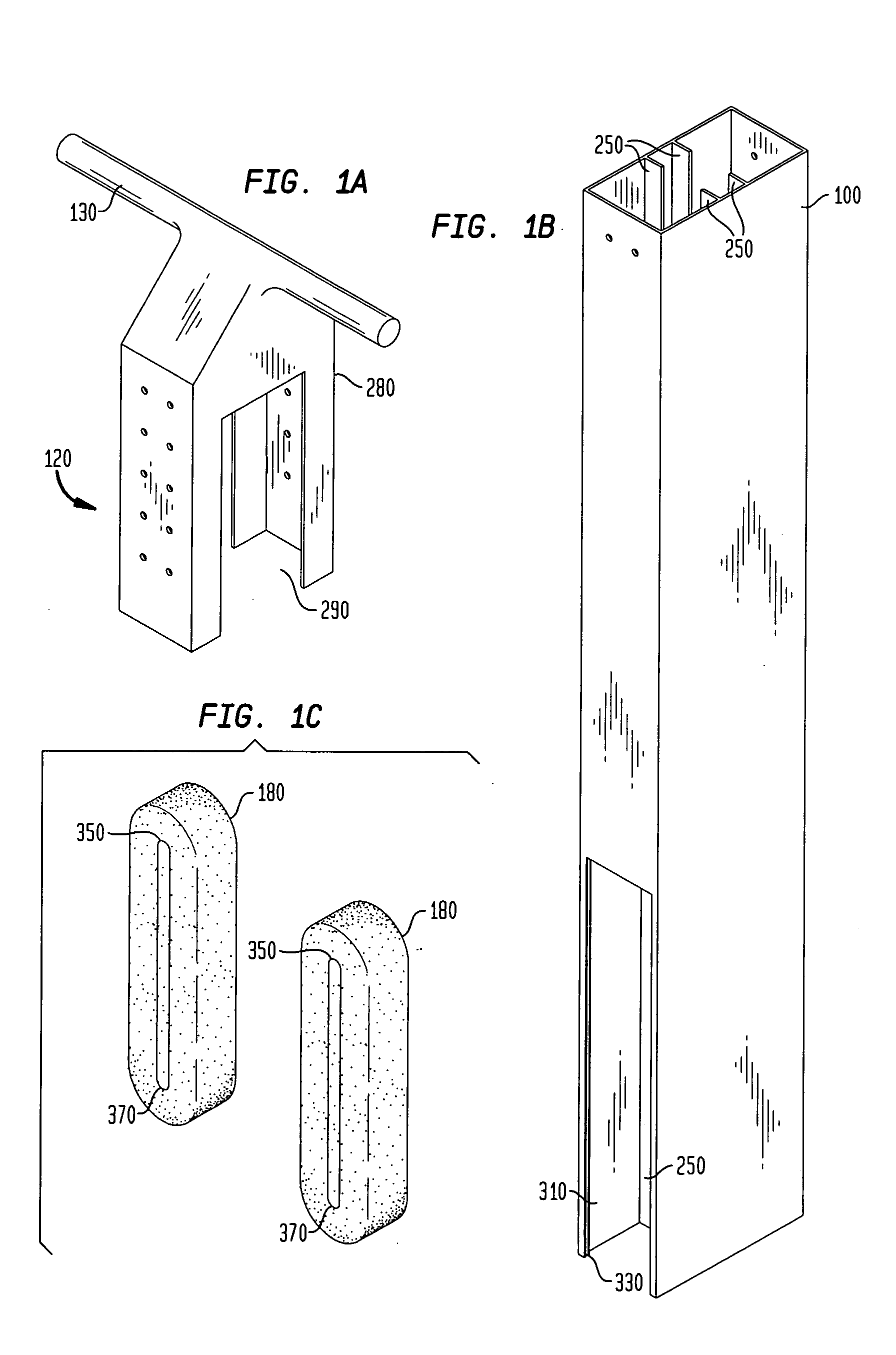
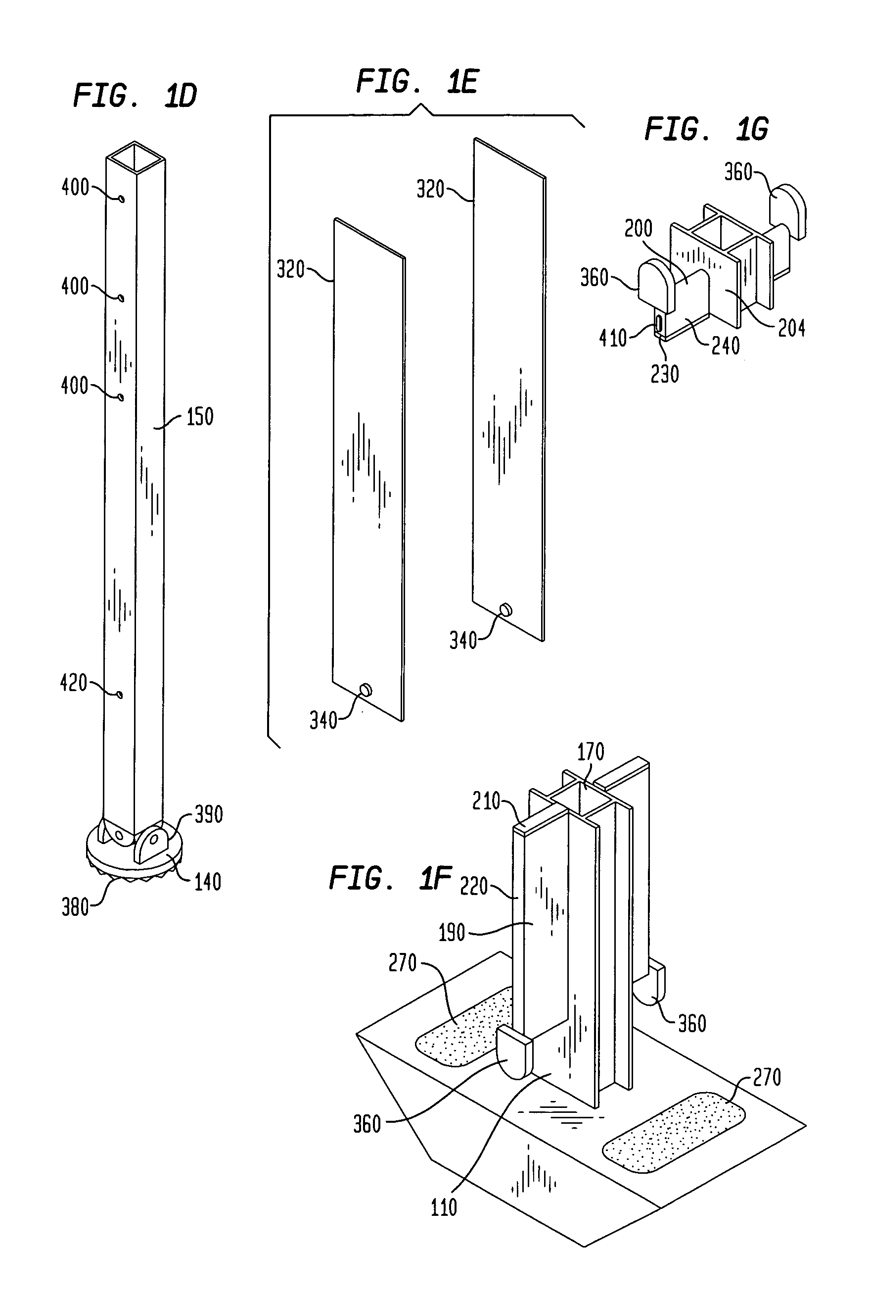
[0070]FIGS. 1a-1g, 2 and 3 illustrate a pogo apparatus which is a preferred embodiment of the invention, in exploded perspective, assembled perspective, and cutaway views. The illustrated pogo apparatus employs a scalable compound elastomer spring, and includes a carriage assembly (including in this embodiment a frame 100, shown in FIG. 1b; a lower insert 110, shown in FIG. 1f; and a telescoping handle assembly 120, shown in FIG. 1a) that can support a rider; a foot 140, shown in FIG. 1d, alternately retracting toward and extending away from the carriage assembly; and a thrust assembly that has a tension force that impels the extension of the foot 140 and resists the retraction of the foot 140. The thrust assembly includes a piston 150, shown in FIG. 1d, having the foot 140 at a distal end; at least one bearing (including in this embodiment a single bearing 170, shown in FIG. 1f) mounted between the carriage assembly and the piston 150 for easing the retraction and extension of the ...


PUM


Abstract

A scalable high-performance bouncing apparatus provides convenient access to untensioned internally semi-mounted springs/tension elements. A holster retains the inoperative semi-mounted elements and avoids contact or friction with fully engaged tension elements. Adjustable connection elements permit compensation for lengthening of spring elements due to creep or elongation set. The connection elements include collars that compress the tension elements, and may be connected to the springs/tension elements by first stretching the elements beyond their working elongation and then placing the collars onto the stretched portions.

Description

CROSS-REFERENCE TO RELATED APPLICATIONS [0001] This application is a continuation-in-part of U.S. patent application Ser. No. 10 / 291,987, filed Nov. 12, 2002, which is a continuation-in-part of U.S. patent application Ser. No. 09 / 799,386, filed Mar. 5, 2001, now U.S. Pat. No. 6,558,265, which claims the benefit of U.S. Provisional Application No. 60 / 187,167 filed Mar. 6, 2000, the entire disclosures of which are hereby expressly incorporated by reference herein.BACKGROUND OF THE INVENTION [0002] This invention relates generally to ridable bouncing apparatuses and more particularly to such apparatuses which achieve high performance, have radically adjustable spring strength or which employ compound elastomer springs or enclosed thrust assemblies. The invention also relates to ridable bouncing apparatuses that provide features for convenient engagement and disengagement of springs / tension elements, as well as semi-mounted internal storage of the springs / tension elements. [0003] Steel-...

Claims


Application Information

Patent Timeline
Patent Type & Authority Applications(United States)
IPC IPC(8): A63B21/055A63B25/08A63G31/00
CPCA63B21/0004A63B21/00065A63B21/0428A63B21/055A63B2208/12A63B21/0555A63B21/0557A63B25/08A63B2208/0204A63B21/0552
Inventor MIDDLETON, BRUCE
Owner FLYBAR
Why Eureka
Try Eureka