Support and enclosure structure for fluorescent light bulbs

a technology for supporting and enclosing structures, which is applied in the direction of light fastenings, transportation and packaging, lighting and heating equipment, etc. it can solve the problems of affecting excessive heat emitted by bulbs, and glass tubes which are very prone to breakage, so as to facilitate the removal and replacement prolong the lifespan of fluorescent light bulbs, and quick and easy removal

Active Publication Date: 2006-05-23
KUTLER MURRAY
View PDF4 Cites 35 Cited by
  • Summary
  • Abstract
  • Description
  • Claims
  • Application Information

AI Technical Summary

Benefits of technology

[0013]As thus described, the support and enclosure structure for fluorescent light bulbs of the present invention provides a substantial improvement over those protective devices found in the prior art. For example, the support and enclosure structure of the present invention may be quickly and easily removed from the fluorescent light fixture and, once removed, the fluorescent light bulb held there within may be replaced while the support and enclosure structure is in a far more accessible location. Once the bulb is replaced, the support and enclosure structure can then be put back into the fluorescent light fixture, thus greatly facilitating the removal and replacement of the fluorescent light bulb. Also, the ventilation opening extending through the outer wall of the hollow tube permits air flow between the inner volume of the tube and the surrounding environment, thus cooling the fluorescent light bulb held therewithin which extends the lifespan of the fluorescent light bulb and greatly reduces the risk of fire due to excessive heat caused by the bulb. Finally, because the hollow tube is constructed of a generally rigid material such as plastic or a resin-based material, there is far less concern with breakage of the fluorescent light bulb during installation and removal from the fluorescent light fixture which greatly reduces the chance for injury due to breakage of the bulb. It is thus seen that the support and enclosure structure for fluorescent light bulbs of the present invention provides a substantial improvement over those devices found in the prior art.

Problems solved by technology

The problem with most fluorescent lights, and, in particular, fluorescent light bulbs, is this glass tube which is very prone to breakage during installation or removal of the fluorescent bulb from the fluorescent light fixture.
Another problem encountered in the use of fluorescent light bulbs is the excessive amount of heat which can be emitted by the bulb, particularly in the case of the currently available high-intensity fluorescent light bulbs.
Unless the heat generated by the bulb is allowed to dissipate, the lifespan of the fluorescent bulb may be severely compromised which detracts from the usefulness of the fluorescent bulb and makes operation of the unit that much more expensive.
It has further been found that the heat dissipation problems encountered with fluorescent light bulbs being used with standard lighting fixtures are exacerbated when the air space surrounding the light bulb is restricted, as would occur if the bulb were contained within a protective enclosure or the like.
However, removal and replacement of the fluorescent bulb entails some degree of danger due to the elongated glass tube which comprises the fluorescent light bulb, as the elongated glass tube is easily shattered and broken by any type of contact or excessive stress.
Furthermore, the ease with which the fluorescent light bulb may be removed and replaced is almost entirely dependent on the location of the fluorescent light fixture, and, in the event of the fluorescent light fixture being in a fairly inaccessible area, removal and replacement of a bulb can be very difficult.

Method used


Image

  • Support and enclosure structure for fluorescent light bulbs
  • Support and enclosure structure for fluorescent light bulbs
  • Support and enclosure structure for fluorescent light bulbs

Examples


Embodiment Construction

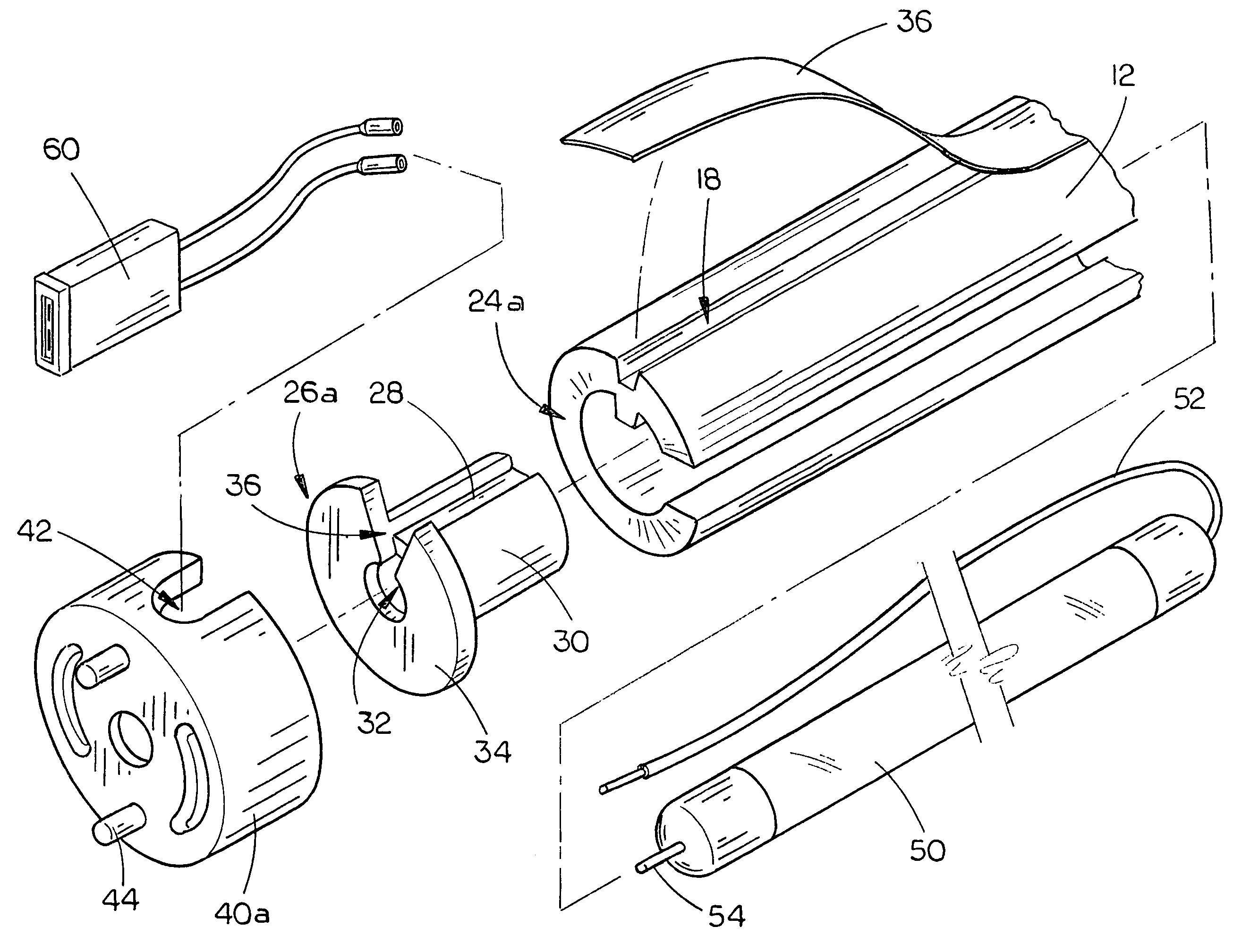
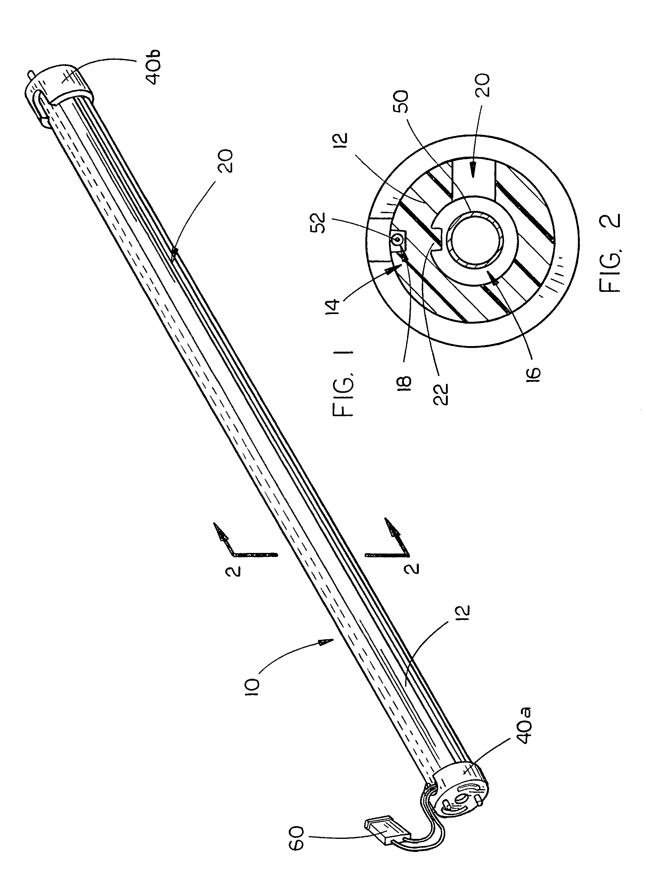
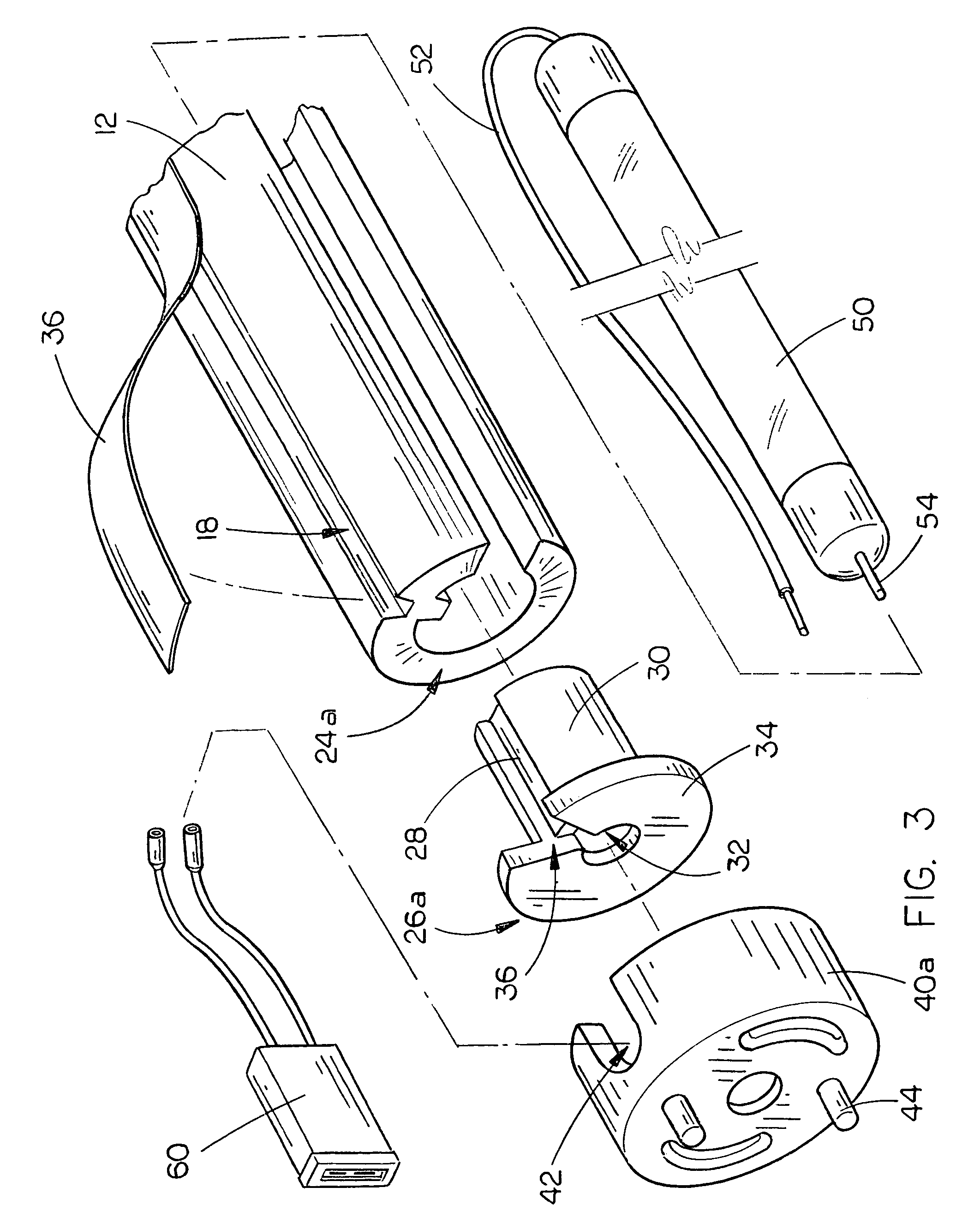
[0019]The support and enclosure structure 10 for fluorescent light bulbs of the present invention is best shown in FIGS. 1–4 as including an elongated hollow tube 12 which, in the preferred embodiment, would have a length of approximately six inches to four feet, and a diameter of approximately one-half inch to three inches, depending on the bulb size which is to be retained within the support and enclosure structure 10. The thickness of outer wall 14 would vary accordingly, although in any circumstance it is preferred that the outer wall 14 be of sufficient thickness to provide structural rigidity to the hollow tube 12 to provide appropriate protection for the fluorescent light bulb 50 retained within the hollow tube 12. It is further preferred that hollow tube 12 be constructed of a sturdy plastic or resin-based material which would be molded into the hollow tube shape by any standard plastic formation technique used in the art. Furthermore, it is preferred that the hollow tube 12...


PUM


Abstract

A support and enclosure structure for fluorescent light bulbs includes an elongated, hollow tube having opposite ends, an outer wall and an inner volume, and at least one ventilation opening extending through the outer wall for permitting air flow between the inner volume of the tube and the surrounding environment for cooling of the fluorescent light bulb held there within. End caps are mounted on opposite ends of the tube, the end caps adapted to engage opposite ends of the fluorescent light bulb and support the fluorescent light bulb within the inner volume of the tube free of contact with the outer wall of the tube. Finally, the tube is constructed of a generally rigid, at least partially translucent materials, such that light emitted by the fluorescent light bulb held within the tube generally radiates through the outer wall of the tube into the surrounding environment.

Description

BACKGROUND OF THE INVENTION[0001]1. Technical Field[0002]The present invention relates generally to support devices for lights and, more particularly, to a support and enclosure structure for fluorescent light bulbs which includes an elongated hollow tube having opposite ends, an outer wall and an inner volume, at least one ventilation opening extending through the outer wall for permitting air flow between the inner volume of the tube and the surrounding environment for cooling of the fluorescent light bulb held within the tube, end caps mounted on opposite ends of the tube which engage the opposite ends of a fluorescent light bulb and support the light bulb within the inner volume of the tube free of contact with the outer wall of the tube and the tube being constructed of a generally rigid, at least partially translucent material such that light emitted by the fluorescent light bulb is viewable through the outer wall of the elongated hollow tube.[0003]2. Description of the Prior ...

Claims


Application Information

Patent Timeline
Patent Type & Authority Patents(United States)
IPC IPC(8): F21V7/20F21V29/02F21V17/06F21V23/06F21V29/00F21V29/505
CPCF21V29/83F21V29/004F21V17/06F21V23/06
Inventor KUTLER, MURRAY
Owner KUTLER MURRAY
Why Eureka
Try Eureka