Newel anchorage system

a new type of anchorage system and anchorage plate technology, applied in the direction of handrails, rod connections, manufacturing tools, etc., can solve the problems of insufficient resistance to deformation, small flanges for floor anchorage, and current building methods and tight production schedules, and avoid the effect of reducing the number of screws and bolts

Inactive Publication Date: 2006-05-23
LANPHIER LEE
View PDF26 Cites 14 Cited by
  • Summary
  • Abstract
  • Description
  • Claims
  • Application Information

AI Technical Summary

Benefits of technology

[0013]Brackets for anchorage of vertical construction members are provided. The brackets connect quickly to newels or other posts, and anchor anywhere on a floor or platform that has been built to code. Selected brackets may support a newel at the end of a balustrade, on the inside or outside corner of a balcony, or on a long balcony run where center support is critical. Selected brackets may secure a starting newel for a curb wall or a landing and simultaneously anchor the wall studding. The brackets are typically job-specific and therefore may satisfy current or future code requirements without costly failure.

Problems solved by technology

However, current building methods and tight production schedules are not conducive to cutting holes in framed flooring, or to building additional support for posts in the joisting.
This type of anchor plate, with its small flanges for floor anchorage, typically exhibits insufficient resistance to deformation, or pull out, when code minimum lateral pressures of 200 lbs. or more are applied at typical hand or guard rail heights.
Bartel's newel anchoring approach (U.S. Pat. No. 6,290,212) involves a specially developed tubular newel that makes it impractical for all but a very limited number of installations.
Though the screws into the sides of the newel provide more pullout resistance than endgrain screws such as those used in Eldeen's anchor, the angled extensions through which the floor-mounting screws are fastened do not offer sufficient resistance to floor pullout when code-level lateral pressures are applied.
Though the screws in the sides of the newel hold well, the flanges that are fastened to the floor do not offer sufficient hold-down strength when the posts are subjected to code-level pressures.
Nicholas' U.S. Pat. No. 5,419,538 provides a novel hidden approach to newel attachment, however the newel post fastening system of Nicholas has no ability to withstand code-level lateral pressures.
This makes this system unpopular with builders who do not want unsightly plugs on their newel posts.
This system is also prone to disassembly of newel posts composed of softer woods or made of multiple staves when code-level pressure is applied.

Method used


Image

  • Newel anchorage system
  • Newel anchorage system
  • Newel anchorage system

Examples


Embodiment Construction

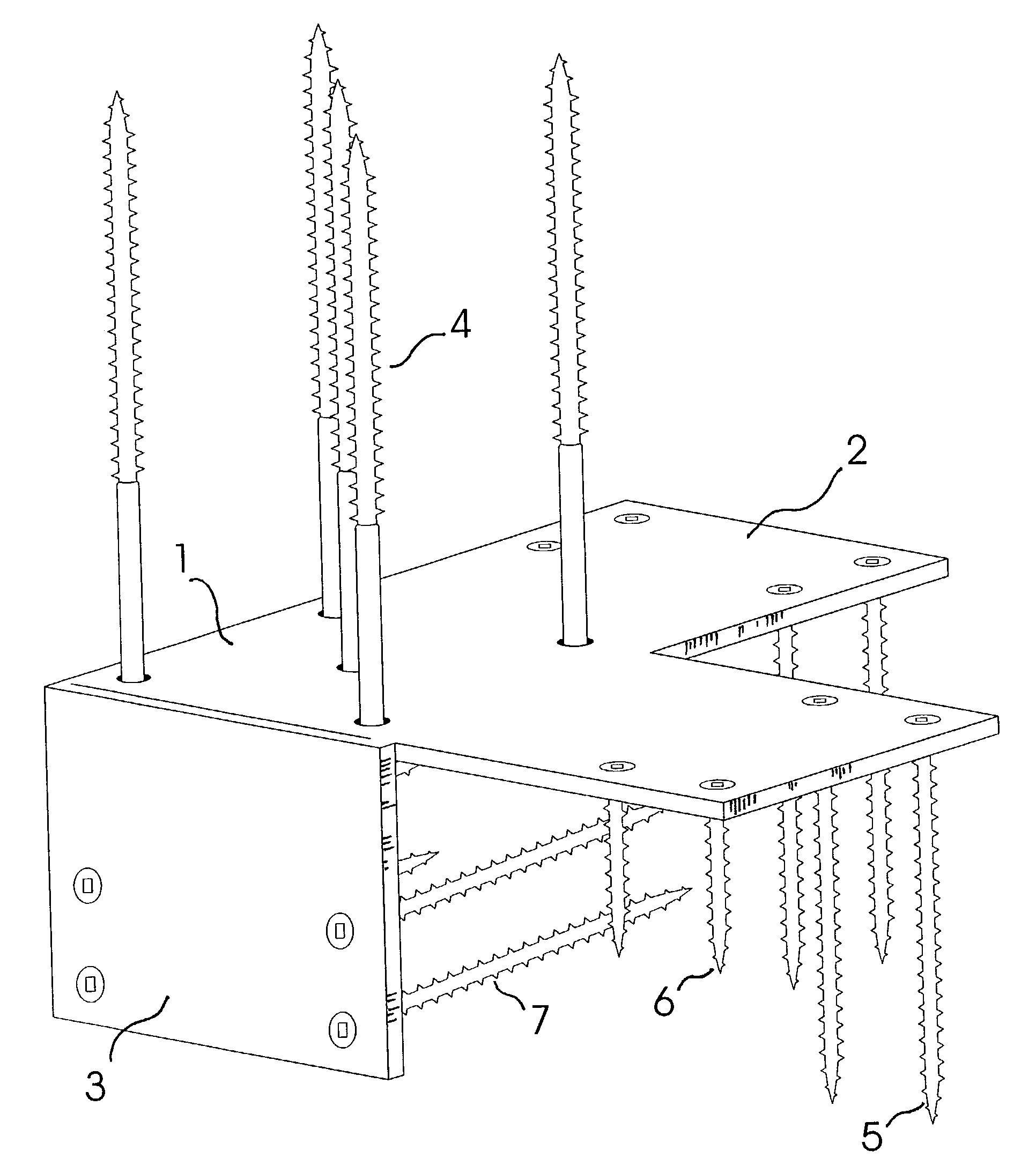
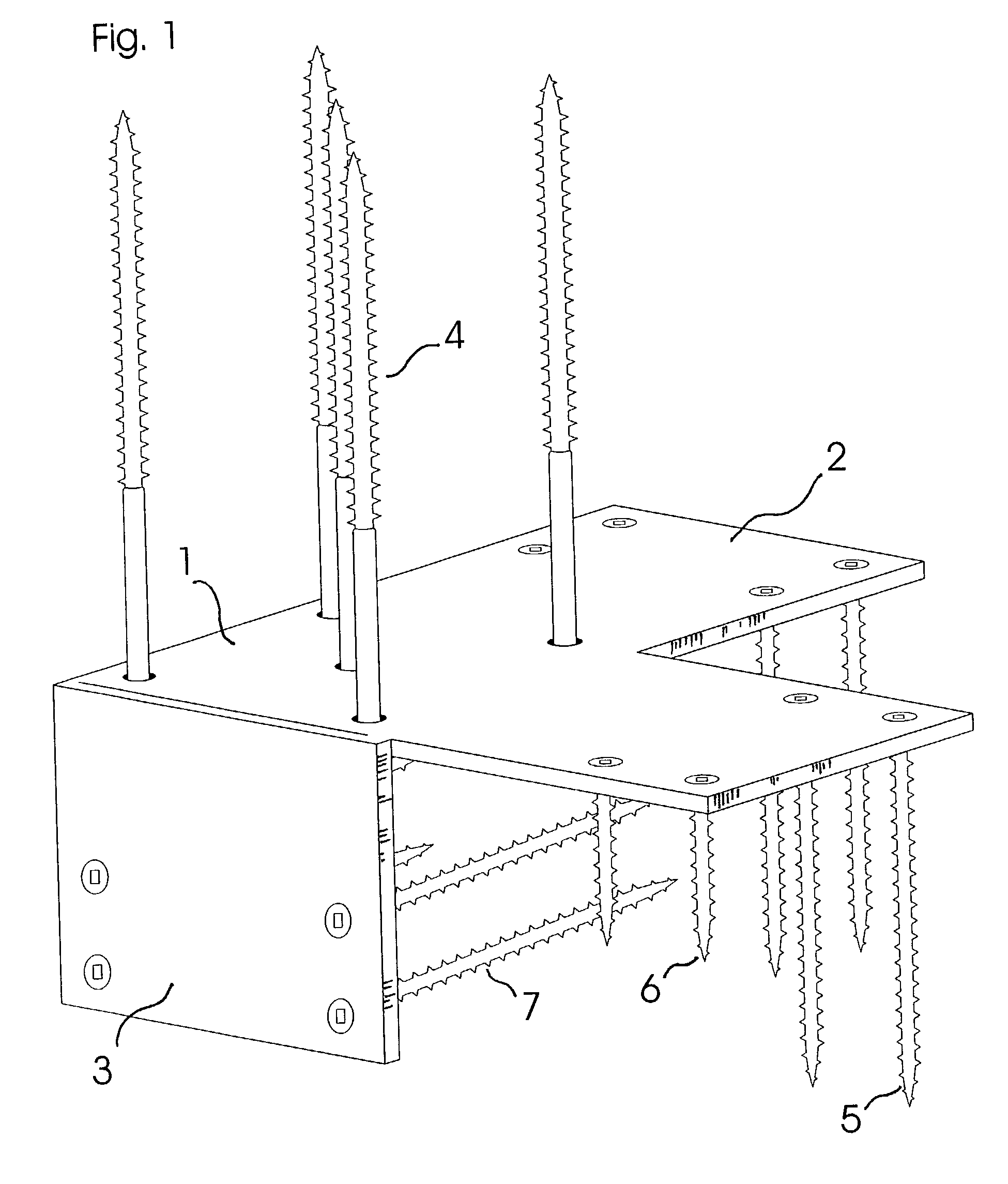
[0047]FIG. 1 provides a close-up view of an Outside Corner Newel-Anchoring Bracket according to a selected embodiment of the invention. The anchoring bracket of FIG. 1 may be formed from 3 / 16″ thick T1 steel, ASTM A514 Grade H, from U.S. Steel, or an equivalent material, and typically includes a plurality of apertures that permit the screw attachment of the bracket to both a newel post and the framing floor or platform.

[0048]The bracket includes a center square portion 1 that mounts to the transverse bottom of the newel. The center square portion of all the brackets that mount to a transverse bottom of a newel, either directly or through a plinth block, typically reach to within ¼″ of the edge of the newel.

[0049]The bracket further includes an extension flange 2 of a size equal to or larger than center square portion 1. This large flange provides increased resistance to downward pressure toward the direction of its extension and increased resistance to lifting pressure from the oppo...


PUM


Abstract

A systematic solution is provided to the anchorage of newel posts designed for building methods that are not conducive to cutting holes in framed flooring or to building in support for posts in the joisting. These brackets connect quickly to newels and anchor anywhere on a floor or platform that has been built to code. They support the newel at the end of a balustrade, on the inside or outside corner of a balcony, or on a long balcony run where center support is critical. They will secure a starting newel for a curb wall or a landing and anchor the wall studding at the same time. Unlike universal brackets, these are job specific and therefore able to meet current or future code requirements without costly failure.

Description

CROSS-REFERENCE TO RELATED APPLICATIONS[0001]This application is based upon and claims benefit under 35 U.S.C. § 119(e) of U.S. Provisional Patent Application Ser. No. 60 / 294,302, entitled “Newel Anchorage System,” filed on May 27, 2001, which is incorporated herein by reference.FIELD OF THE INVENTION[0002]The present invention relates generally to the construction of stairs, and more particularly to brackets for anchoring newels to a floor or platform.BACKGROUND OF THE INVENTION[0003]Newel posts for stairways and level balustrades are typically anchored only at the bottom, but must withstand tremendous lateral forces applied at hand or guard rail height. Builders have traditionally cut through treads and floors in order to fasten newel posts as much as possible directly to the underlying joisting. However, current building methods and tight production schedules are not conducive to cutting holes in framed flooring, or to building additional support for posts in the joisting. As a r...

Claims


Application Information

Patent Timeline
Patent Type & Authority Patents(United States)
IPC IPC(8): E04F11/18
CPCE04F11/1804E04B1/2608E04F2011/1887Y10T403/33Y10T403/4602Y10T403/3906Y10T403/7096E04F11/1812F16B2200/503F16B2200/67
Inventor LANPHIER, LEE
Owner LANPHIER LEE
Why Eureka
Try Eureka