Cranial bone flap fixation

a cranial bone flap and fixation technology, applied in the field of cranial surgery apparatus and methods, can solve the problems of requiring a considerable amount of time and added cost, and affecting the stability of the fixation method

Active Publication Date: 2006-05-23
BIOPLATE
View PDF16 Cites 43 Cited by
  • Summary
  • Abstract
  • Description
  • Claims
  • Application Information

AI Technical Summary

Benefits of technology

[0007]c) at least the first cap having protruding structure to extend into a gap formed between the cranial bone and the bone flap to laterally orie

Problems solved by technology

In some cases, fixation with wire or suture material is not secure.
Shifting of the bone flap may result in dislocation, causing depression

Method used


Image

  • Cranial bone flap fixation
  • Cranial bone flap fixation
  • Cranial bone flap fixation

Examples


Embodiment Construction

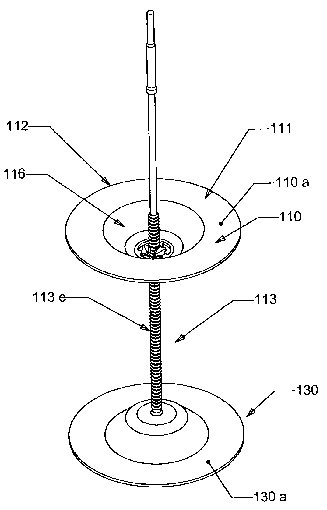
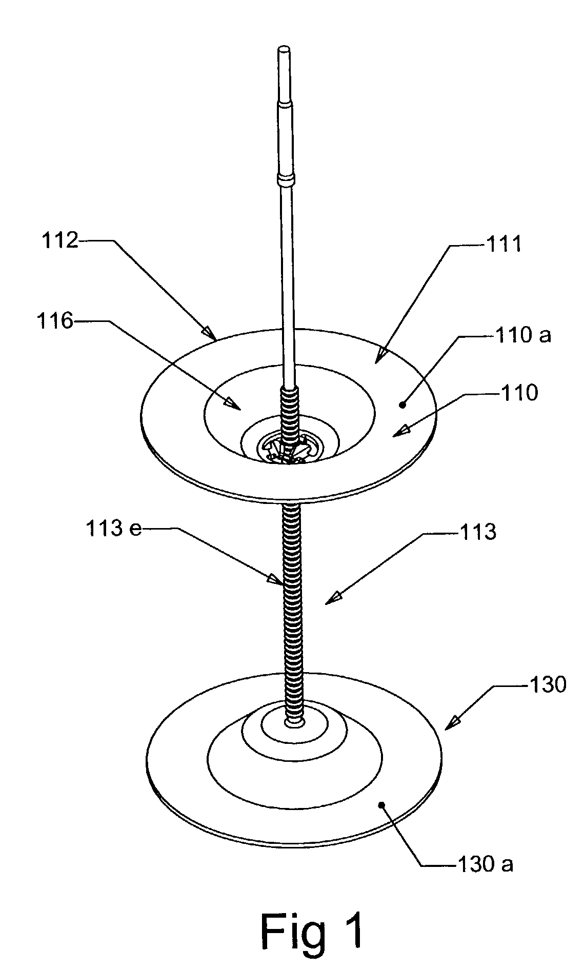
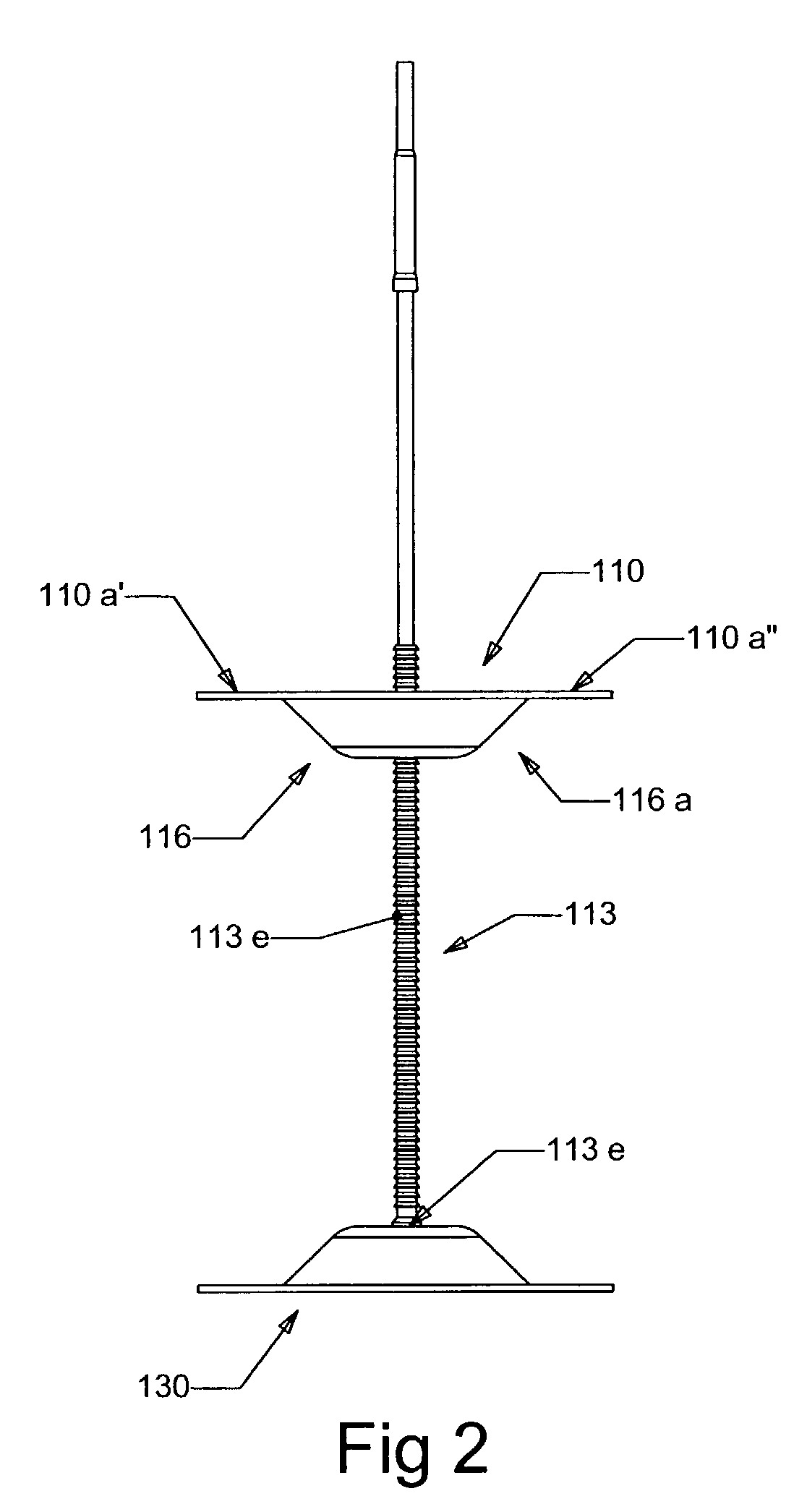
[0018]FIGS. 1–4 show a form of the invention, which is preferred. An upper cap 110 in the form of a disc has an outer portion 110a extending about the axis of post 113. One arcuate segment 110a′ of portion 110a is intended to engage top surface 119a of a cranial bone flap 119; and a second arcuate segment 110a″ of portion 110a is intended to engage top surface 118a of cranial bone 118. See FIG. 4. Similarly, a lower cap 130 has an outer portion 130a extending about the post, with arcuate segments 130a′ and 130a that engage bottom surfaces 119c and 118c of 119 and 118. See FIG. 6.

[0019]During installation, the upper cap is relatively displaced toward the lower cap, and the caps are tightened against upper and lower surfaces of the cranial bone 118 and bone flap 119. Typically, the lower cap is pulled upwardly toward and against undersides of the flap and cranial bone, during upper cap lowering. Afterwards, the post is severed, adjacent the top surfaces of the upper cap, as seen at 13...


PUM


Abstract

A cranial bone and bone flap fixation device, comprising first and second caps between which portions of the cranial bone and bone flap are to be gripped; a longitudinally extending mounting post located to allow relative cap movement lengthwise of an axis defined by the post at least the first cap having protruding structure to extend into a gap formed between the cranial bone and the bone flap to laterally orient the first cap so that peripheral portions thereof will extend over both the cranial bone and the bone flap during fixation.

Description

BACKGROUND OF THE INVENTION[0001]This invention relates generally to cranial surgery apparatus and method, and more particularly to implant systems and methods for re-fixation of cranial bone flaps after craniotomy.[0002]Cranial bone flaps after craniotomy are typically fixed in position with wire, suture material or mini plates and screws. In some cases, fixation with wire or suture material is not secure. Shifting of the bone flap may result in dislocation, causing depression or protrusion of the flap relative to the adjacent cranium. This phenomenon occurs more frequently with the progressive shift to smaller craniotomies for minimally invasive surgical procedures.[0003]Fixation of the bone flap using mini plates and screws has improved the attachment of the bone flap. This technique, however, demands a considerable amount of time and added cost. There is need for an improved system for fixation of the bone flap to the cranium, providing for quick and easy application, optimal st...

Claims


Application Information

Patent Timeline
IPC IPC(8): A61B17/58
CPCA61B17/688
Inventor WELLISZ, TADEUSZ Z.ABIDIN, CIN K.GRAY, DEAN
Owner BIOPLATE
Why Eureka
Try Eureka