

Intraocular lenses
a technology of intraocular lens and lens frame, which is applied in the field of intraocular lens, can solve the problems of affecting the design of the optical part, affecting the function of the lens frame, and generating an increase in the intraocular pressure, so as to reduce the edge glare and undesired halo or cusp effect, the design freedom of the optical part is greater, and the effect of reducing edge glar
- Summary
- Abstract
- Description
- Claims
- Application Information
AI Technical Summary
Benefits of technology
Problems solved by technology
Method used
Image

Examples
example 1
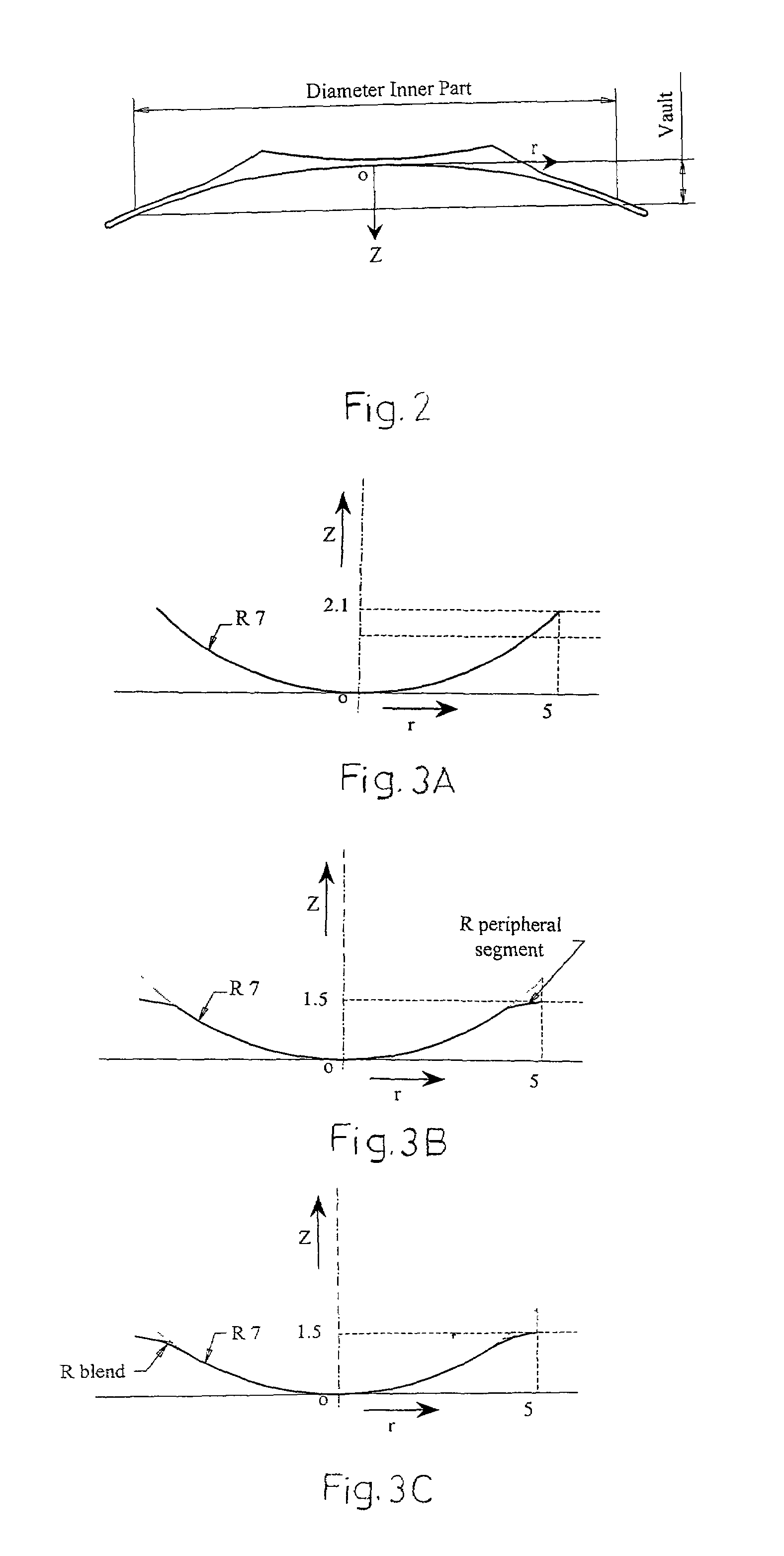
[0062]After estimation of the front radius of the natural lens of a patient, a 7 mm central posterior radius of the correction lens implant is selected. This selection enables that any adherence to the natural lens is avoided. In order to avoid any contacts with the natural lens, the correction lens should rest on the zonulas and vault over the natural lens. The vault is defined in accordance with FIG. 2. A vault of 1.5 mm is assumed to be sufficient to avoid contact, both with the accommodated and the non-accommodated natural lens. Should the posterior surfaces be spherical with a radius of 7 mm over 9 mm, the central vault of the correction lens is 2.1 mm as shown in FIG. 3A which is too large when considering the dimensions of the posterior chamber. In order to reduce the vault, the posterior surface is constructed from circle segments. The central circle segment thereby represents the posterior surface of the optical part and the peripheral segment represents the posterior surfa...
example 2
[0063]A large radius of curvature of 14.5 mm is selected to avoid adherence with the central radius of the natural lens. A spherical posterior surface is drafted with 10 mm in diameter, a radius of curvature of 14.5 mm and a central vault of 0.9 mm. To obtain a central vault of 1.5 mm, the surface is constructed as an oblate spheroid following the formula:
z=cvr2 / (1+√{square root over ((1−cv2(cc+1)r2))})
with a conic constant cc=7.2. A rotation symmetric surface according to FIG. 5 is obtained with a 1.5 mm vault of the implant over a diameter of 10 mm. This surface will vault sufficiently over the natural lens and if the implanted lens will be pressed against the natural lens, there will be nor risk of adherence. Since the posterior surface will be flawless, the risk of stress concentration is eliminated. FIG. 6 shows an alternative design of a rotation symmetric posterior correction lens surface, according to which a curve is constructed in r-Z plane having a central circle segment ...
example 3
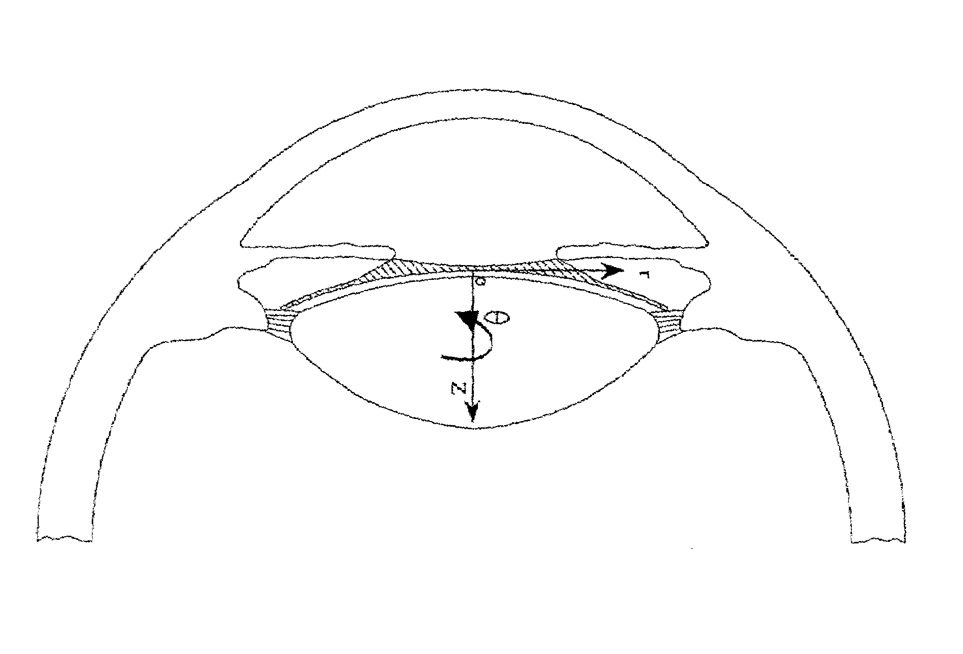
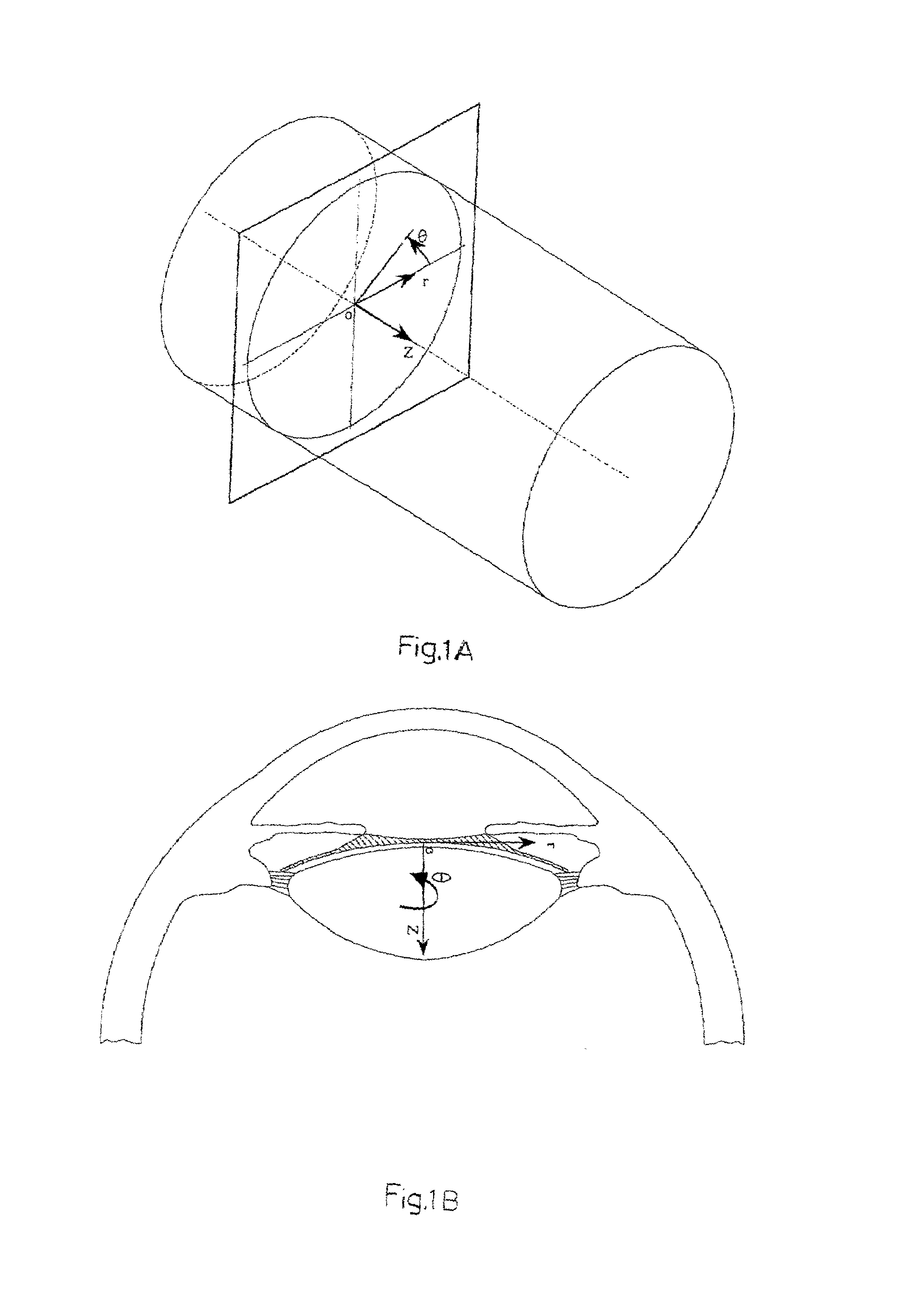
[0064]FIG. 7 shows a correction lens 10 lathe cut from a co-polymer of N-benzyl-N-methacrylamide with a refractive index of 1.49. The co-polymer is produced in accordance with U.S. Pat. No. 5,717,049. The lens has a maximum diameter of 12.5 mm and a central circular optical part 12 with a diameter of 6 mm and a support element 14. The support element consist of an inner part 15 surrounding the optical part and two peripheral parts 16 and 16′ which after implantation will placed in the region of the ciliary sulcus of the eye and contribute to keep the lens in a central location. In this embodiment, the inner part has a diameter of 10 mm. The peripheral parts are each provided with a centrally located concave indentation 17, 17′ that provide a free area for fluid circulation close to the ciliary sulcus.
[0065]FIG. 8 shows a crossectional plane containing the optical axis along arrows A–A′ in FIG. 1. The intersection between this plane and the posterior surface of the lens represents a ...
PUM
 Abstract
Description
Claims
Application Information