Screwdriver having release mechanism

a technology of release mechanism and screwdriver, which is applied in the direction of screwdrivers, rod connections, wrenches, etc., can solve the problems of inconvenience for users when taking or placing tips, and achieve the effect of reducing disadvantage and/or obviating disadvantag

Inactive Publication Date: 2006-05-30
CHEN YI YING +2
View PDF3 Cites 65 Cited by
  • Summary
  • Abstract
  • Description
  • Claims
  • Application Information

AI Technical Summary

Benefits of technology

[0006]The primary objective of the present invention is to provide a screwdriver having a release mechanism that is operated easily, rapidly and conveniently.
[0007]Another objective of the present invention is to provide a screwdriver, wherein the holding seat and the end cap are removed from the main body easily and rapidly, thereby facilitating the user taking or placing the tips mounted in the mounting holes of the holding seat.
[0008]A further objective of the present invention is to provide a screwdriver, wherein the user only needs to press the push button of each of the two push button sets of the release mechanism so as to detach the holding seat and the end cap from the main body, thereby facilitating the user removing the holding seat and the end cap from the main body.

Problems solved by technology

However, the user has to exert a larger force to remove the end cap from the main body or to rotate the end cap relative to the main body to unscrew the end cap from the main body so as to remove the end cap from the main body, thereby causing inconvenience to the user when taking or placing the tips.

Method used


Image

  • Screwdriver having release mechanism
  • Screwdriver having release mechanism
  • Screwdriver having release mechanism

Examples


Embodiment Construction

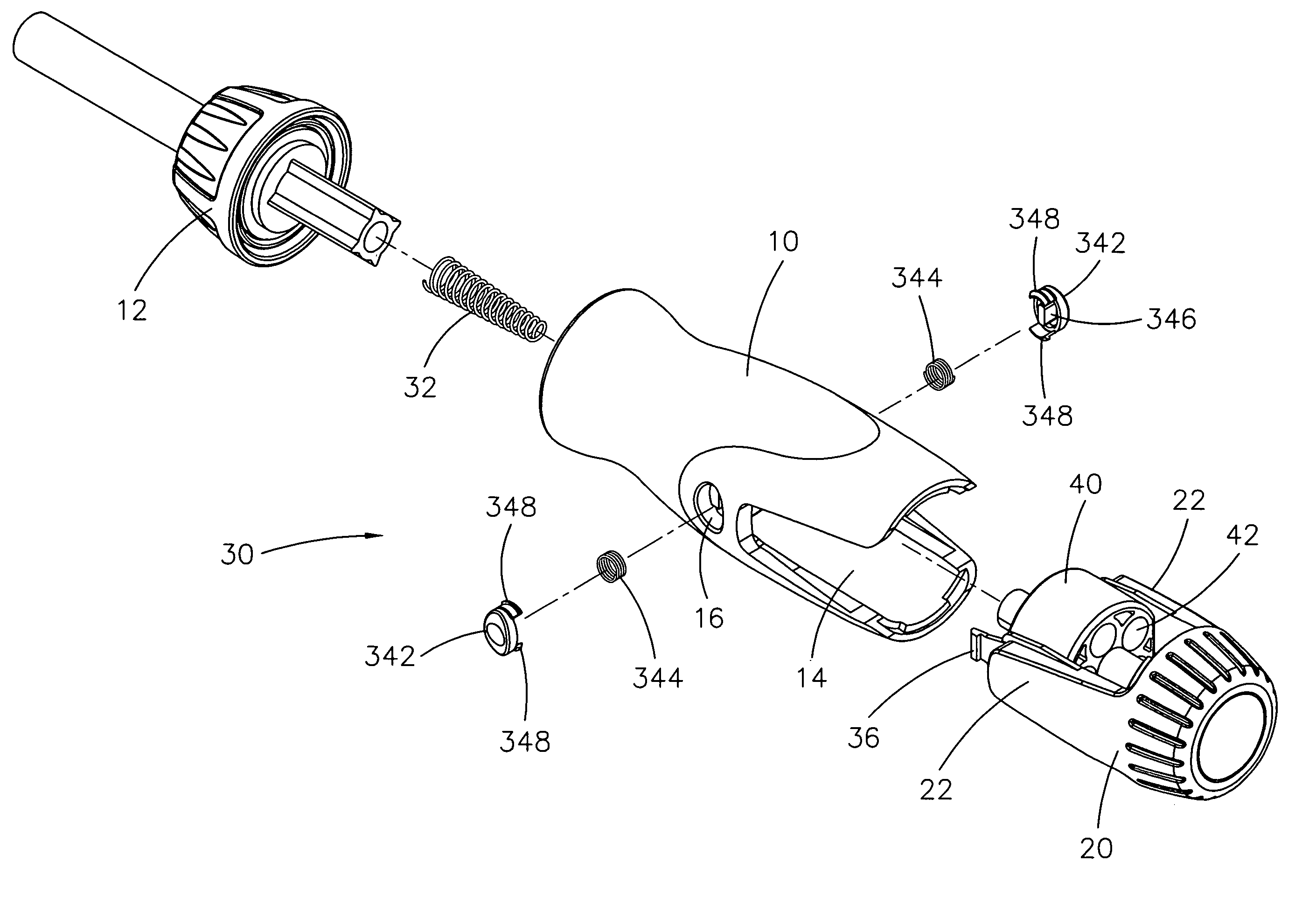
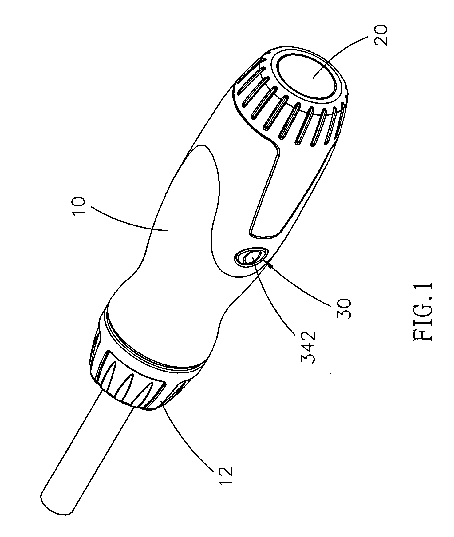
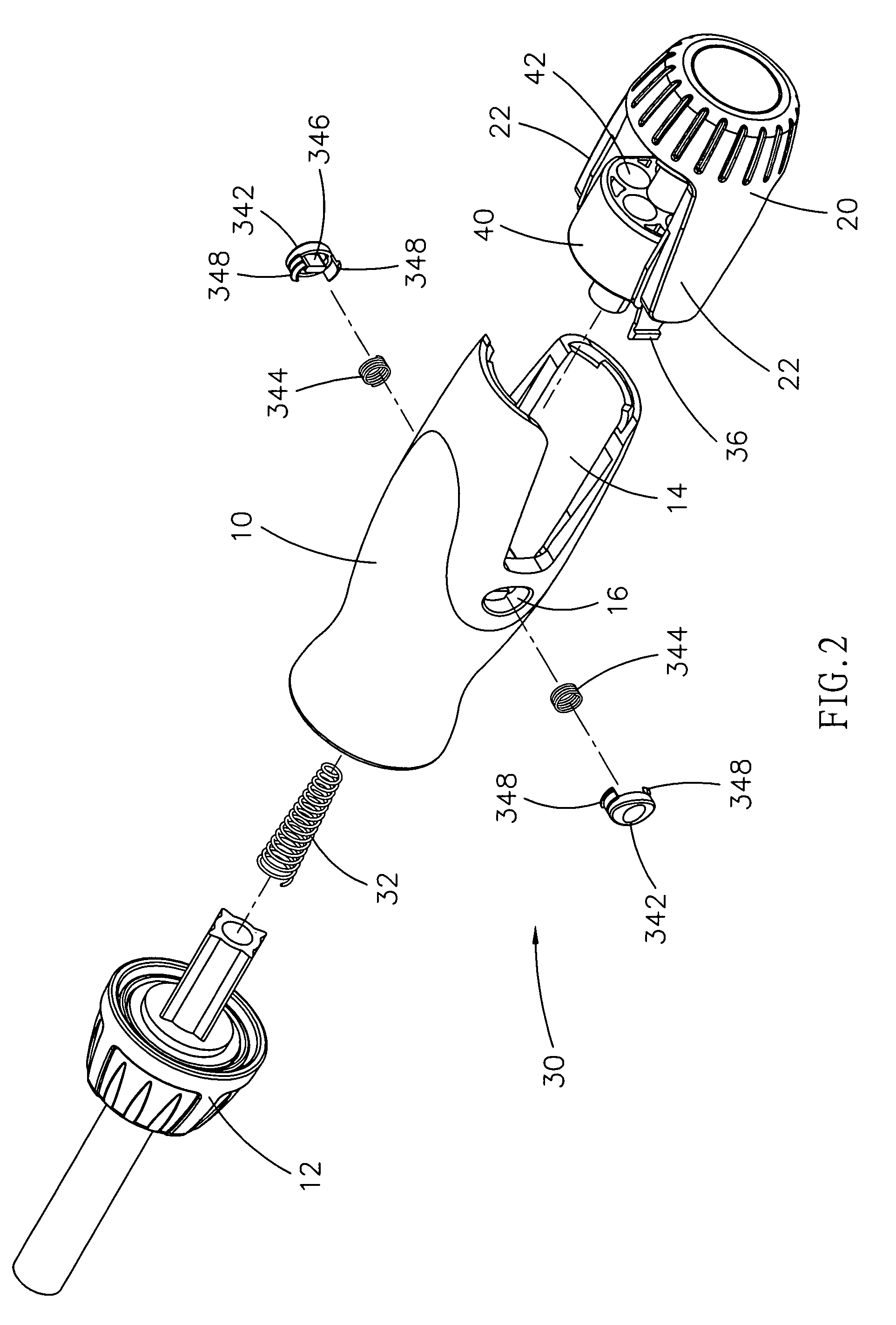
[0021]Referring to the drawings and initially to FIGS. 1–3, a screwdriver in accordance with the preferred embodiment of the present invention comprises a main body 10, an end cap 20, a holding seat 40, and a release mechanism 30.

[0022]The main body 10 has a first end formed with a hollow receiving chamber 14 and a second end provided with a connecting stem 12 to connect tips 50 (see FIG. 6) of different types.

[0023]The end cap 20 is removably mounted on the first end of the main body 10 to close the receiving chamber 14 of the main body 10 and has two side walls 22 each received in the receiving chamber 14 of the main body 10.

[0024]The holding seat 40 is pivotally mounted on the end cap 20 between the two side walls 22 and received in the receiving chamber 14 of the main body 10. The holding seat 40 has a plurality of axially extended mounting holes 42 for mounting a plurality of tips 50 (see FIG. 6).

[0025]The release mechanism 30 includes an axial spring 32, two push button sets 3...


PUM


Abstract

A screwdriver includes a main body, an end cap, a holding seat, and a release mechanism. Thus, the holding seat and the end cap are removed from the main body easily and rapidly, thereby facilitating the user taking or placing the tips mounted in the mounting holes of the holding seat. In addition, the user only needs to press the push button of each of the two push button sets of the release mechanism so as to detach the holding seat and the end cap from the main body, thereby facilitating the user removing the holding seat and the end cap from the main body.

Description

BACKGROUND OF THE INVENTION[0001]1. Field of the Invention[0002]The present invention relates to a screwdriver, and more particularly to a screwdriver having a release mechanism.[0003]2. Description of the Related Art[0004]A conventional screwdriver comprises a main body having a first end formed with a receiving chamber to receive tips of different types and a second end provided with a connecting stem to connect the tips of different types, and an end cap closely fitted or screwed into the first end of the main body to close the receiving chamber of the main body. However, the user has to exert a larger force to remove the end cap from the main body or to rotate the end cap relative to the main body to unscrew the end cap from the main body so as to remove the end cap from the main body, thereby causing inconvenience to the user when taking or placing the tips.SUMMARY OF THE INVENTION[0005]The present invention is to mitigate and / or obviate the disadvantage of the conventional scr...

Claims


Application Information

Patent Timeline
Patent Type & Authority Patents(United States)
IPC IPC(8): B25B23/00B25G1/00B25G1/08B25B23/16B25G3/18
CPCB25G1/085Y10T403/535
Inventor CHEN, YI YINGCHEN, SIOU RULIN, SU FEN
Owner CHEN YI YING
Why Eureka
Try Eureka