Adjustable vascular ring and implantable kit comprising such a ring

Pending Publication Date: 2021-04-22
MEDICAL INNOVATION DEV
View PDF4 Cites 0 Cited by
  • Summary
  • Abstract
  • Description
  • Claims
  • Application Information

AI Technical Summary

Benefits of technology

[0009]In this context, the invention proposes a device for controlling the circulation flow rate of a fluid inside a biolo

Problems solved by technology

It causes a lethal alteration of the liver.
It is clear that such a compression of the portal vein is equivalent to crushing, causing a stenosis which leads to turbulences in the blood flow resulting in risks of thrombosis.
This implant according to WO2010/102661A do

Method used


Image

  • Adjustable vascular ring and implantable kit comprising such a ring
  • Adjustable vascular ring and implantable kit comprising such a ring
  • Adjustable vascular ring and implantable kit comprising such a ring

Examples


Example

[0051]The following description of a preferred embodiment of the ring according to the invention, will highlight other remarkable features.

[0052]This detailed description is given with reference to the attached figures in which:

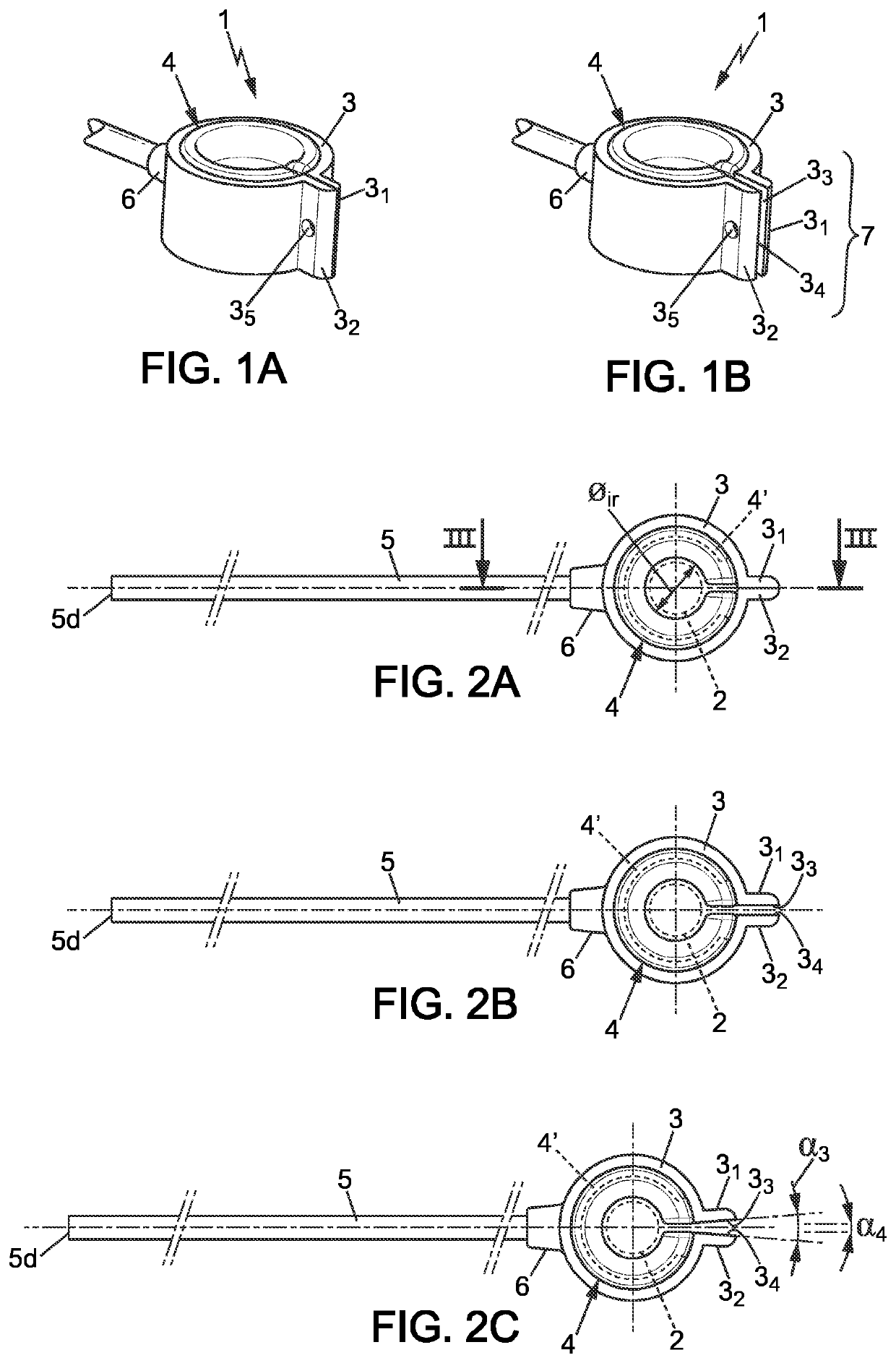
[0053]FIGS. 1A & 1B represent perspective views of the ring according to an embodiment, deflated and in the closed and open positions respectively.

[0054]FIGS. 2A, 2B & 2C represent top views of the ring, at rest and respectively in closed (2A) and open positions according to a preferred embodiment (FIG. 2C) and according to an embodiment variant (FIG. 2C), ready to be positioned around the duct.

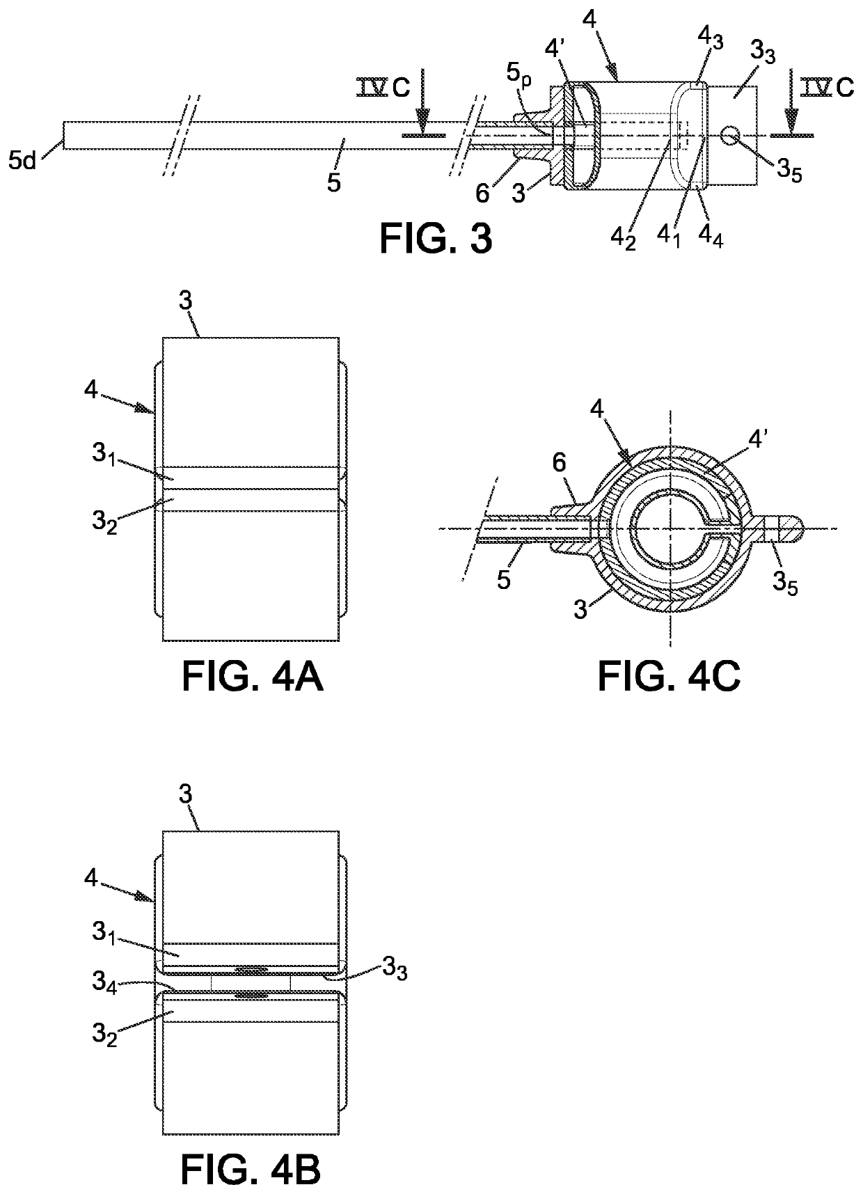
[0055]FIG. 3 is a longitudinal cross-sectional view along the cutting plane III-III of FIG. 2A, 2B or 2C.

[0056]FIGS. 4A & 4B are front views of the ring shown in FIG. 2A & 2B or 2C respectively.

[0057]FIG. 4C is a longitudinal cross-sectional view along the cutting plane IV-IV of FIG. 3,

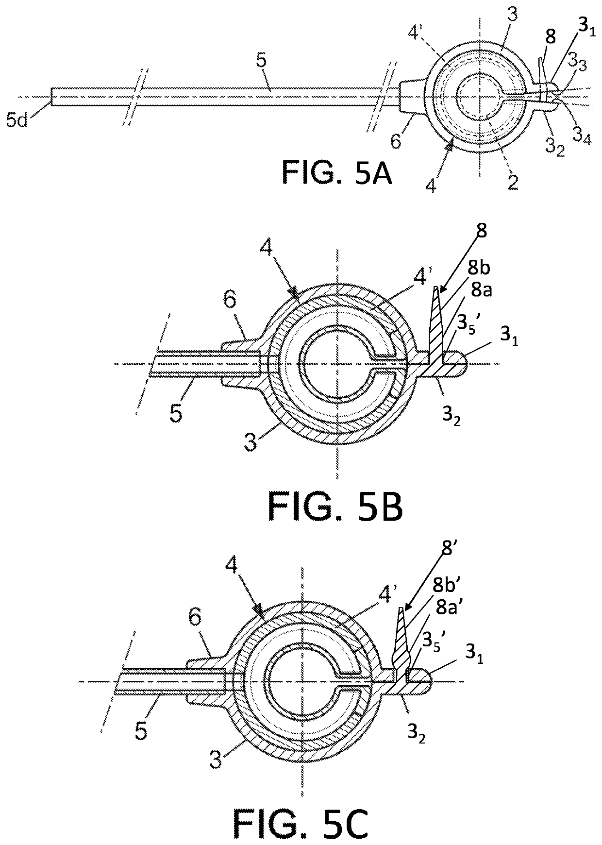
[0058]FIGS. 5a and 5b are top views of another embodiment of the ring with closing m...


PUM


Abstract

Ring comprising:
    • an outer belt (3) equipped with closing means (7) for closing the ring (1) around a duct (2);
    • an inner chamber (4) that can be inflated and deflated;
    • a flexible inflation/deflation tube (5);
wherein the lips have contact surfaces facing each other, the closing means comprising at least one perforation arranged on the contact surface of a first of the two lips and at least one protrusion protruding from the contact surface of a second of the two lips, the protrusion and the perforation being configured so that the protrusion is retained in the perforation by fitting, the fitting being selected to be released in the event of overpressure in the ring.

Description

TECHNICAL FIELD[0001]The field of the invention is that of medical devices that can be implanted by surgical route around a biological duct, in particular a vessel and more particularly a blood vessel such as the portal vein, in order to allow adjustment of the diameter of the duct and therefore of the flow rate of a fluid (blood) capable of circulating therein.[0002]These implantable medical devices are more precisely vascular rings that can be inflated and deflated using a fluid, so as to adjust their inner diameter and thus the inner diameter of the ducts / vessels around which they are intended to be implanted.[0003]The invention also relates to the kit that can be implanted by surgical route and allow control of the inner diameter of a vessel and, as a result, the flow rate of a fluid circulating therein.TECHNOLOGICAL BACKGROUND OF THE INVENTION[0004]It is known to implant medical devices constituted by inflating banding rings, around blood vessels of patients in order to restric...

Claims


Application Information

Patent Timeline
IPC IPC(8): A61B17/12
CPCA61B17/12A61B17/135A61B17/12013A61B17/12009A61B2017/00557A61B2017/00778A61B17/12036A61B17/1204A61B17/12136A61B2017/12018A61B2017/00915
Inventor CAZENAVE, LUDOVIC
Owner MEDICAL INNOVATION DEV
Why Eureka
Try Eureka