Medical instrument

a technology of medical instruments and instruments, applied in the field of medical instruments, can solve the problems of requiring a large installation and dismantling effor

Active Publication Date: 2014-06-10
KARL STORZ GMBH & CO KG
View PDF20 Cites 0 Cited by
  • Summary
  • Abstract
  • Description
  • Claims
  • Application Information

AI Technical Summary

Benefits of technology

[0006]The accomplishment of this object by means of the invention is characterized in that the pivotable partial area of the gripping member can be removably secured by a catch mechanism to the rigid partial area of the gripping member and that the catch mechanism comprises a catch hook, which is configured so that it can be actuated by a push-button.
[0007]Owing to the inventive configuration of a catch mechanism for installing and dismantling the pivotable partial area, it is possible without use of tools to remove the pivotable partial area easily and rapidly, in particular for cleaning purposes, and to secure it again to the rigid partial area.
[0008]According to a practical embodiment of the invention, it is proposed that the catch mechanism should comprise a spring-loaded push-button that is equipped with a catch hook and is positioned on one of the components that are to be connected by catching with one another, and a locking element, in particular a lock bolt, that is positioned on the other component and corresponds with the catch hook. This configuration of the catch mechanism as a catch hook and corresponding locking element, in particular a lock bolt, constitutes an embodiment of the inventive catch mechanism that is particularly simple to produce and to handle.
[0010]In order, first, to make possible a smooth-running pivoting motion of the pivotable partial area around the rigid partial area and, second, to be able to adjust the friction resistance individually, it is further proposed with the invention that the sliding and locking bushing should include a pivot bearing that is non-pivotably connected with the push-button as well as a sliding bushing that interacts with the pivot bearing and is connected non-pivotably with the pivotable partial area.
[0016]It is finally proposed with the invention that the pivot angle of the pivotable partial area should be limited by the mounting of the pivotable partial area, which is eccentric with respect to the longitudinal axis of the gripping member, on the rigid partial area. Limiting the pivot angle of the pivotable partial area of the gripping member is advantageous in preventing any slippage of the gripping member in the operator's hand.

Problems solved by technology

This type of pivotable configuration of a gripping member of the handle has proved itself in the art; however, it involves very considerable installation and dismantling effort to remove the pivotable partial area of the gripping member from the rigid gripping member for cleaning purposes and / or to reconnect it again.

Method used


Image

  • Medical instrument
  • Medical instrument
  • Medical instrument

Examples


Embodiment Construction

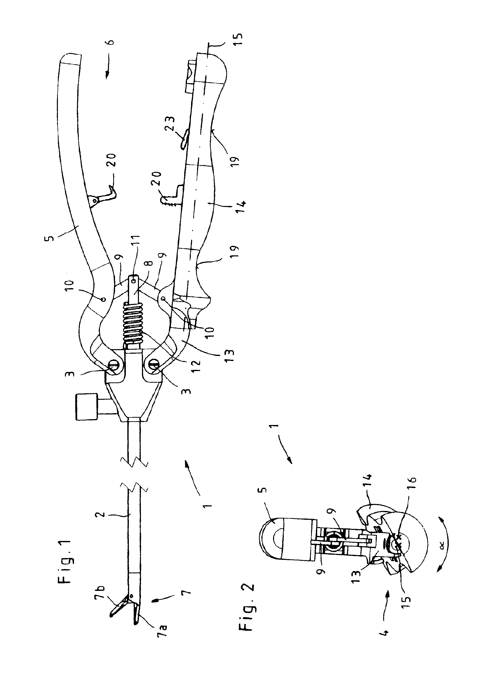
[0022]The first illustration (FIG. 1) shows the side views of a medical instrument 1 that is configured as a gripping and / or cutting instrument and whose power transmission mechanism has many possible applications, such as for example for punching, cutting, needle holding, gripping instruments, and the like.

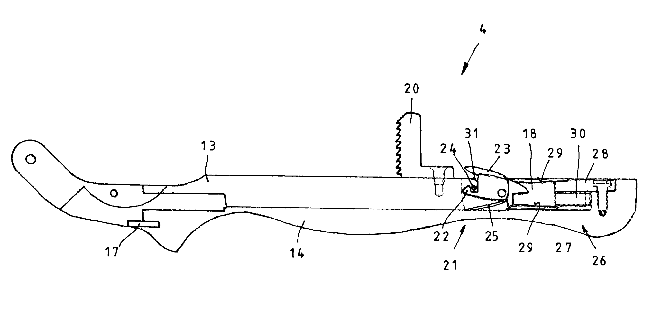
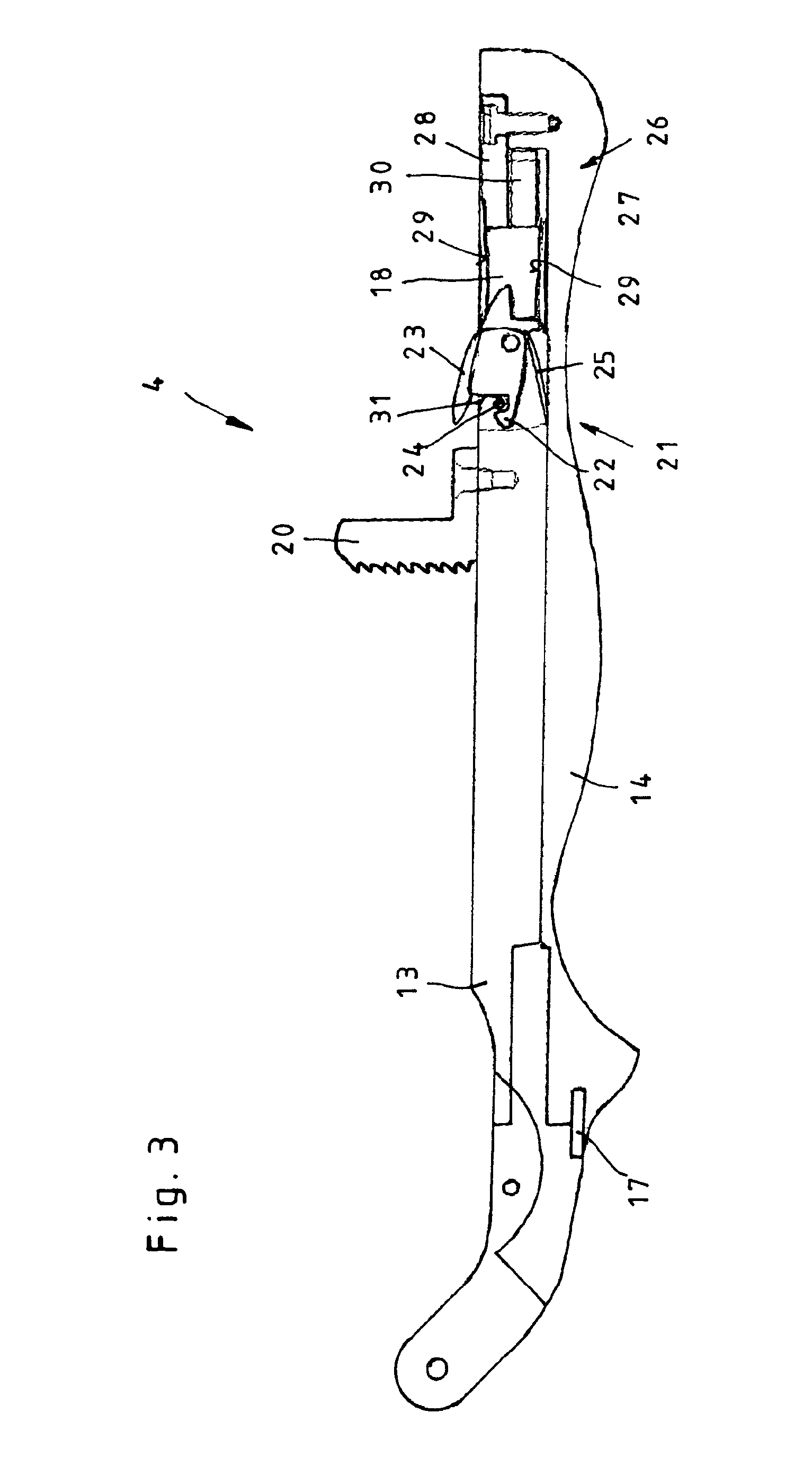
[0023]The illustrated medical instrument 1 consists essentially of a hollow shaft 2 on whose proximal end a handle 6 is positioned consisting of two gripping members 4 and 5 that can each pivot around related pivot axes 3. Positioned on the distal end of the shaft 2 is a tool 7, which in the illustrated embodiment consists of a jaw member 7a rigidly connected with the shaft 2 and a pivotable jaw member 7b. To open and close the jaw members 7a and 7b of the tool 7 by the actuation of the pivotable gripping members 4 and 5 of the handle 6, the gripping members 4, 5 and the pivotable jaw member 7b are in active connection with one another by means of a push-pull rod 8.

[0024]As can f...


PUM


Abstract

A medical instrument with a shaft on whose distal end a tool is positioned and on whose proximal end a handle is positioned consisting of at least two gripping members, such that the tool can be actuated by a gripping member of the handle that is moveably configured and such that at least one gripping member of the handle consists of a rigid partial area and a pivotable partial area that can pivot around the rigid partial area. To create a medical instrument that is of simple structure and can be quickly and thoroughly cleaned, it is proposed with the invention that the pivotable partial area of the gripping member can be removably affixed to the rigid partial area of the gripping member by a catch mechanism.

Description

CROSS-REFERENCE TO RELATED APPLICATIONS[0001]The present application claims priority of German patent application No. 10 2009 025 663.6 filed on Jun. 17, 2009, the content of which is incorporated herein by reference.FIELD OF THE INVENTION[0002]The invention relates to a medical instrument with a shaft on whose distal end a tool is positioned and on whose proximal end a handle is positioned consisting of at least two gripping members, such that the tool can be actuated by a moveably configured gripping member of the handle and such that at least one gripping member of the handle consists of a rigid partial area and a partial area that can pivot around the rigid partial area.BACKGROUND OF THE INVENTION[0003]A generic medical instrument is known, for instance, from DE 10 2005 027 418 A1. Owing to the configuration of one partial area of a handle as a partial area that can pivot around the longitudinal axis of the gripping member, it is possible with this known instrument, without rele...

Claims


Application Information

Patent Timeline
Patent Type & Authority Patents(United States)
IPC IPC(8): A61B17/00B62K21/26
CPCA61B2017/291A61B17/2841A61B2017/00424A61B17/2909Y10T74/20828
Inventor SCHNEIDER, SVEN
Owner KARL STORZ GMBH & CO KG
Why Eureka
Try Eureka