Method and device for controlling an internal combustion engine

a technology of internal combustion engine and control device, which is applied in the direction of electric control, ignition automatic control, instruments, etc., can solve the problems of inability to accurately calculate the torque of calculated basic variables, inability to take into account the different slopes of the correlation between ignition angle and the ignition state, and inability to achieve accurate torque calculation. calculation, the effect of simplifying the model's application

Inactive Publication Date: 2006-05-30
ROBERT BOSCH GMBH
View PDF15 Cites 5 Cited by
  • Summary
  • Abstract
  • Description
  • Claims
  • Application Information

AI Technical Summary

Benefits of technology

[0012]Taking the inert-gas rates and / or charge-movement effects into account when determining the optimum torque for an internal combustion engine within the framework of a torque model, improves and, in particular, simplifies the model's application and shortens the computing time. Furthermore, by taking the operating point into account in correcting the optimum ignition angle as a function of the inert-gas rate, the working-point dependency of this correction is considered and the torque model substantially improved.
[0013]This measure may yield a very accurate indicated engine torque calculated with the aid of the model even when high overlap of the intake and discharge valves is present and / or high inert-gas rates at low charges of the internal combustion engine. The improved model is therefore believed to be particularly suited for internal combustion engines having continuously adjustable intake and discharge valves, or intake and discharge valves that are adjustable by switching, or for internal combustion engines having external exhaust-gas recirculation.
[0015]It may be particularly advantageous that a torque model is provided that considerably improves the accuracy of the torque model as well as the match between the optimum ignition angle and the ignition angle of the best (maximum) torque. It is especially advantageous that this model is invertible, i.e., that it not only allows a calculation of a setpoint ignition angle at a given setpoint torque and a given charge, but also the calculation of a setpoint charge at the given setpoint torque and given basic ignition angle efficiency, as well as a calculation of the actual torque.
[0016]In what be an especially advantageous manner, the torque model for calculating the indicated engine torque is distinguished by high precision even for highly divergent ignition curves and by excellent agreement between the optimizing variable of the optimum ignition angle and the ignition angle at the best possible torque.
[0017]Furthermore, simple applicability of the basic ignition angle actually to be set is achieved, and the model may be used for all engine configurations, that is, for engines having exhaust recirculation, variable camshaft control, variable valve lift, valve shutoff and / or charge-movement flap.

Problems solved by technology

The above-discussed torque model, in particular, may fail to deliver satisfactory results in some operating states.
Furthermore, these are operating states having high charge movements.
Since these effects are not sufficiently taken into account, the calculated basic variables may not achieve an accurate torque calculation when these other procedures are utilized.
Moreover, it is also problematic that the above-discussed model, while considering essential influences on the ignition angle in determining the maximum torque, may fail to take into account the different slopes of the correlation between ignition angle and the maximum engine torque able to be attained in the instantaneous operating point of the engine in different mixtures.
A population for the model, in particular for the optimum ignition angle, cannot be found by the available optimizer of the model parameters, so that the torque model exhibits low tolerance across the entire ignition-angle range.

Method used


Image

  • Method and device for controlling an internal combustion engine
  • Method and device for controlling an internal combustion engine
  • Method and device for controlling an internal combustion engine

Examples


Embodiment Construction

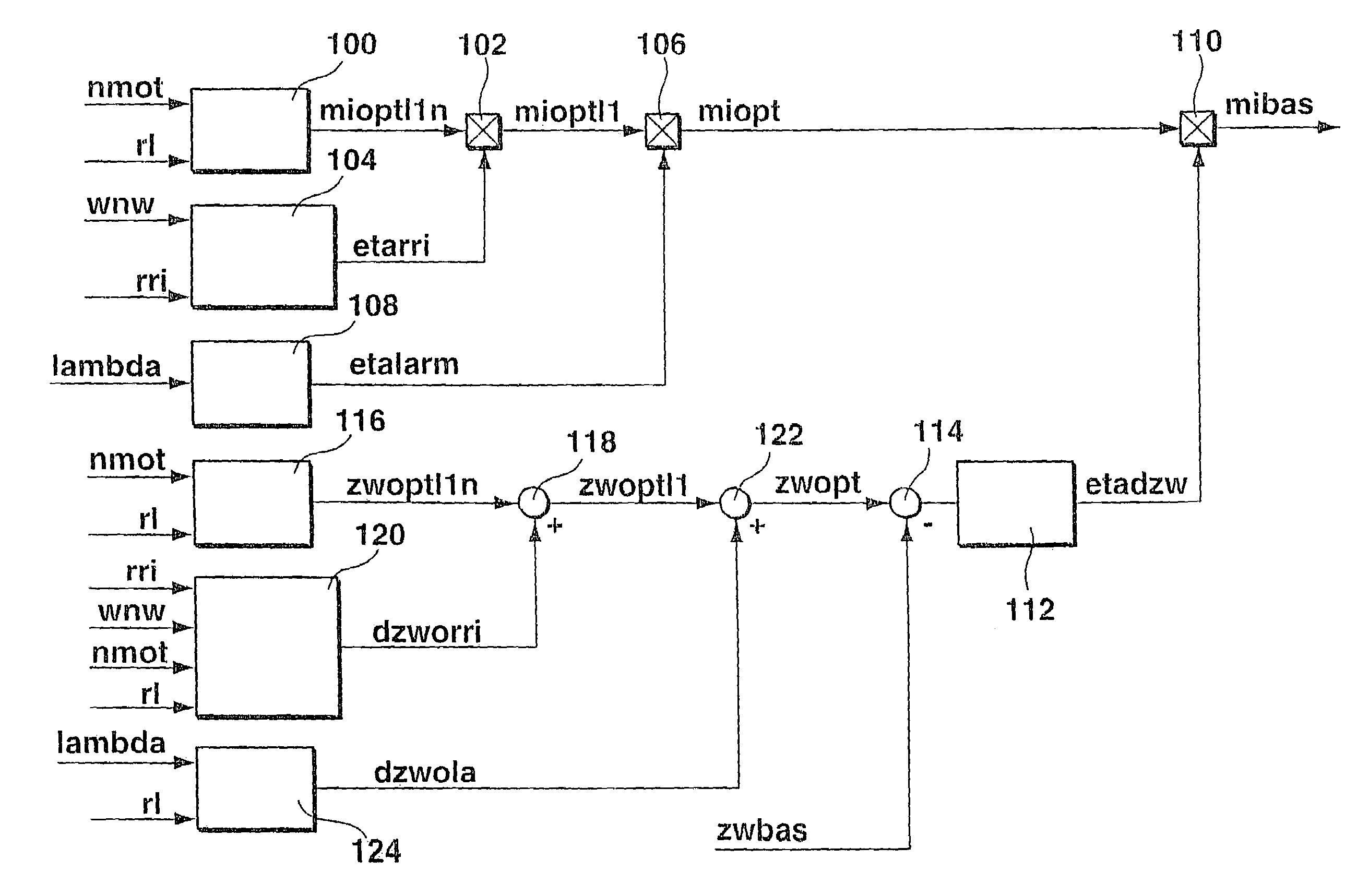
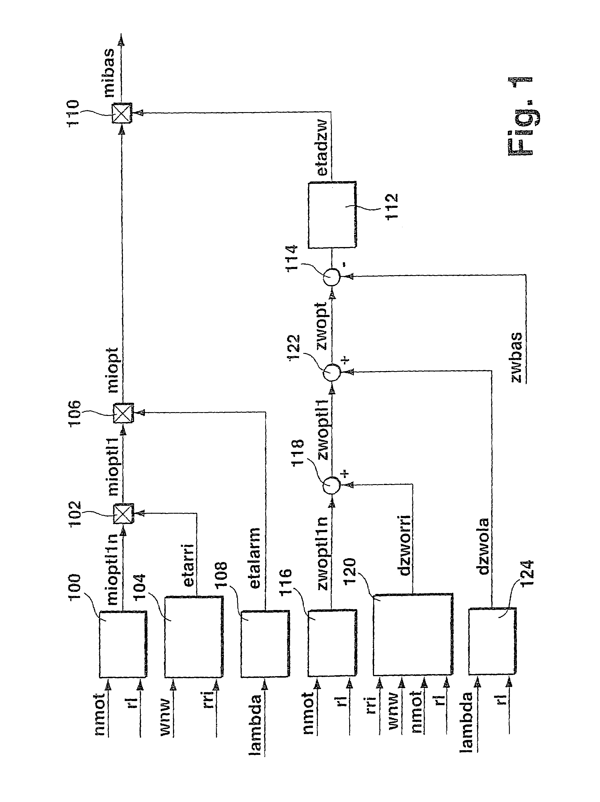
[0025]FIG. 1 shows a flow chart of a first exemplary embodiment for improving the torque model. FIG. 1 describes a program of a microcomputer, the individual elements of the drawing in FIG. 1 representing programs, program steps or program parts, while the arrows describe the flow of information. Shown is the calculation of the actual basic torque, i.e., the torque that results when the basic ignition angle is set, which is selected from a characteristics map as a function of speed and load.

[0026]A correction of the optimum torque value takes place in the model shown in FIG. 1, taking the inert-gas rate and the charge movement into account, and a correction of the optimum ignition angle value, taking the inert-gas rate and the charge movement into consideration, and thus the instantaneous working point.

[0027]In a first ignition map 100, a value mioptlln for the optimum torque is read out as a function of engine speed nmot and actual charge rl, which is determined from the measured a...


PUM


Abstract

A method, a device and a computer program for controlling an internal combustion engine, in which a torque model is used within the framework of calculating instantaneous variables and / or actuating variables. In doing so, a basic value ascertained under standard conditions is corrected as a function of the inert-gas rate and / or the valve-overlap angle. Moreover, to further improve the accuracy of the model, the efficiency for the conversion of the chemical energy into mechanical energy by which the optimum torque value is corrected, is determined as a function of the deviation between optimum ignition angle and an instantaneous ignition angle as well as an additional variable representing the combustion performance of the mixture. The latter is the optimum ignition angle.

Description

RELATED APPLICATION INFORMATION[0001]This application, which is the U.S. national phase application for PCT / DE02 / 03311, filed Sep. 6, 2002, claims priority to and the benefit of German patent application no. 101 49 477.7, filed on Oct. 8, 2001.[0002]1. Field of the Invention[0003]The present invention is directed to a method, a device, and a computer program for controlling an internal combustion engine.[0004]2. Background Information[0005]To control an internal combustion engine, German patent publication no. 42 39 711 (which corresponds to U.S. Pat. No. 5,558,178) refers to converting a setpoint value for a torque of the internal combustion engine into an actuating variable for influencing the air supply to the internal combustion engine, for setting the ignition angle and / or for suppressing or connecting the fuel supply to individual cylinders of the internal combustion engine. In addition, the control of the fuel / air ratio for realizing the predefined torque value is referred to...

Claims


Application Information

Patent Timeline
Patent Type & Authority Patents(United States)
IPC IPC(8): F02P5/15F02D41/04G06F19/00F02D13/02F02D37/02F02D41/14F02D45/00
CPCF02D13/0261F02D37/02F02D41/1497F02P5/1516F02D41/0062F02D41/0072Y02T10/18F02D2200/1004F02D2250/18Y02T10/46F02D2041/001Y02T10/12Y02T10/40F02D41/14
Inventor HOCHSTRASSER, PATRICKSAUER, CHRISTINAESTEGHLAL, GHOLAMABASMALLEBREIN, GEORGKLEIN, EBERHARD
Owner ROBERT BOSCH GMBH
Why Eureka
Try Eureka