Portable vibratory screed with vibration restraint

a vibratory screed machine and vibration restraint technology, which is applied in the direction of roads, building material handling, construction, etc., to achieve the effect of extending the life of the engine and reducing undesirable vibration

Active Publication Date: 2006-05-30
WACKER NEUSON CORP
View PDF8 Cites 13 Cited by
  • Summary
  • Abstract
  • Description
  • Claims
  • Application Information

AI Technical Summary

Benefits of technology

[0009]The present invention provides an improved portable vibratory screed having a vibration restraint configured to reduce undesirable vibration on the engine and to extend the engine's life. The apparatus is ideally suited for use with wet screeds, but is usable with other vibratory screed machines as well.
[0012]The resulting portable vibratory screed machine of the present invention has several advantages over prior vibratory plate machines. The vibratory plate does not interfere with or hinder normal operation of the portable vibratory screed machine. Further, the vibratory plate reduces the imposition of undesirable vibrations on the engine and thereby extends the engine life.
[0013]In accordance with a third aspect of the invention, the present invention provides a method of extending a life of an engine having a drive shaft configured to drive a portable vibratory assembly. The engine is mounted on a reference structure of the portable vibratory screed machine. The method includes the acts of operating the engine to drive the vibratory assembly to generate vibrations, and restraining the engine relative to the vibratory assembly in a direction generally parallel to a central axis of the drive shaft. The act of restraining can include providing a restraint having a first end and a second end, coupling the first end of the restraint to the engine, and coupling the second end of the restraint to the reference structure.

Problems solved by technology

Further, the vibratory plate reduces the imposition of undesirable vibrations on the engine and thereby extends the engine life.

Method used


Image

  • Portable vibratory screed with vibration restraint
  • Portable vibratory screed with vibration restraint
  • Portable vibratory screed with vibration restraint

Examples


Embodiment Construction

[0023]A wide variety of vibration restraints for screeds could be constructed in accordance with the invention as defined by the claims. Hence, while preferred embodiments of the invention will now be described with reference to a portable vibratory wet screed machine, it should be understood that the invention is in no way so limited. For instance, it is also usable with a variety of different vibratory screed machines that are potentially subject to undesired engine vibration.

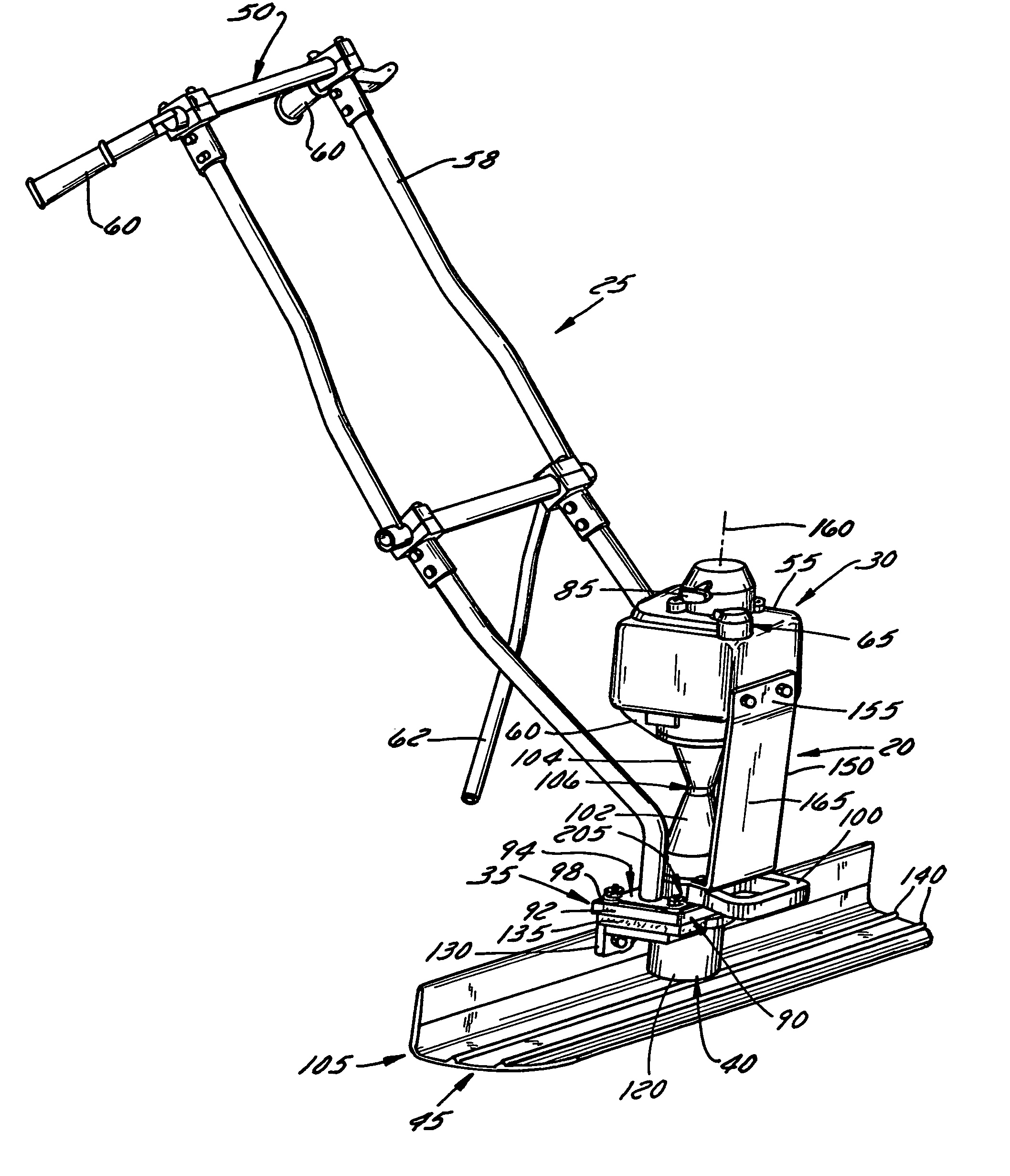
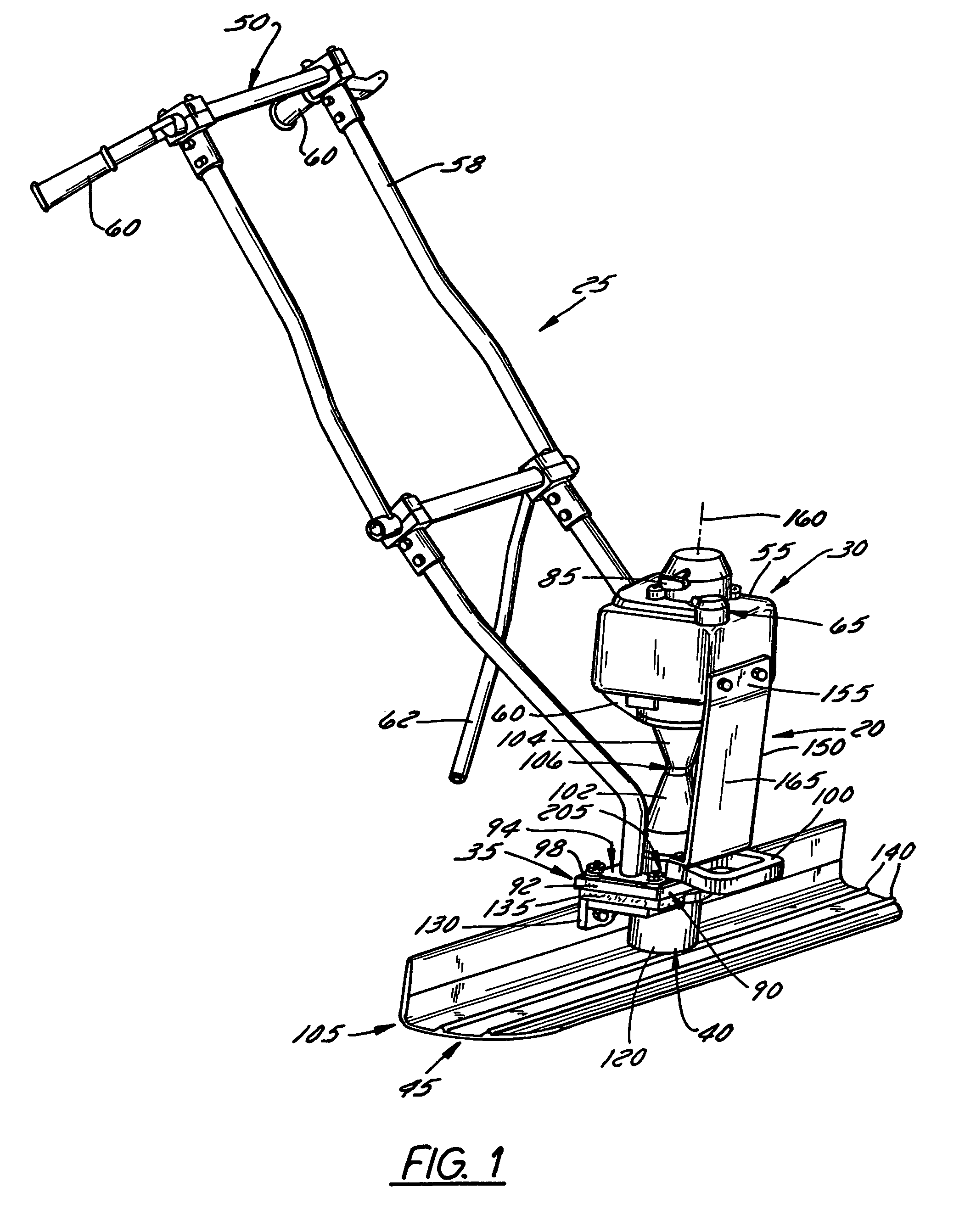
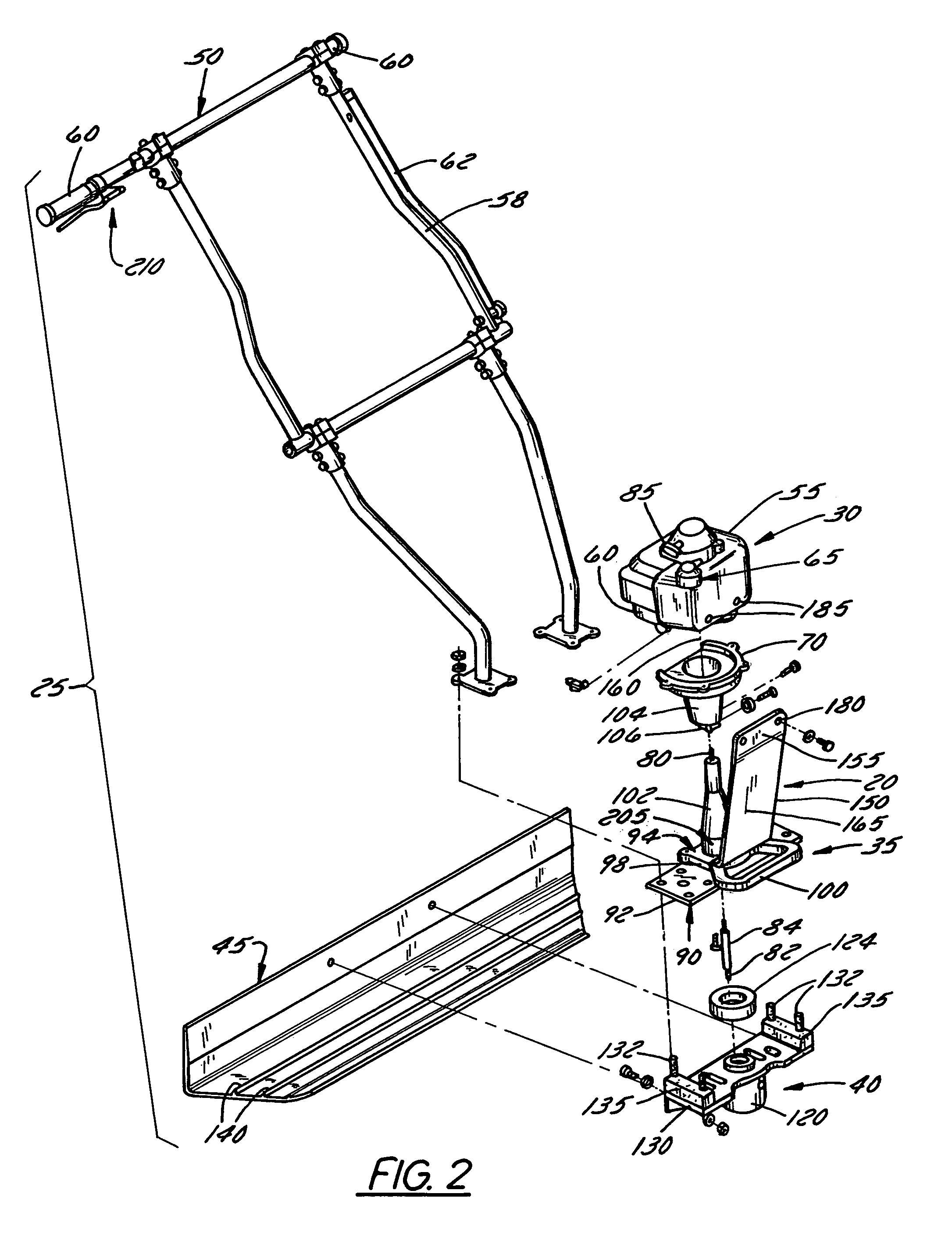
[0024]FIG. 1 illustrates a perspective view of a vibration restraint 20 constructed in accordance with one embodiment of the invention and coupled to a portable vibratory wet screed machine 25. In general, the portable vibratory screed machine 25 includes an engine 30 mounted on a frame 35. The machine 25 further includes an elongated surfacing screed blade 45 coupled to a vibratory assembly 40. The engine 30 is operable to power the vibratory assembly 40 to impart vibratory movement to the blade 45 such that...


PUM


Abstract

A portable vibratory screed machine is provided with a vibration restraint operable to reduce undesirable vibration of the engine and to extend the life of the engine. The portable vibratory screed machine includes a machine frame having a reference structure. The machine further includes an engine mounted on the reference structure via a mount that surrounds a drive shaft that is driven by the engine's output. A vibratory assembly remotely located from the engine is powered by the engine to vibrate a screed plate. The vibration restraint directly couples the engine housing to the reference structure at a location that is spaced apart from the mount.

Description

BACKGROUND OF THE INVENTION[0001]1. Field of the Invention[0002]The invention relates to a portable vibratory screed machine, and, more particularly, relates to a portable vibratory screed machine having a vibration restraint configured to reduce undesirable vibrational wear on and extend the life of the machine's engine.[0003]2. Discussion of the Related Art[0004]Numerous screed machines employ vibratory action to tamp and smooth concrete in the strike off step of a concrete finishing operation. Known vibratory screed machines comprise, for instance, an elongated blade extending horizontally and transversally at lower ends of a pair of handles adapted to be hand held and operated for displacing the wet screed over a concrete surface. A motor is provided above the blade and between the handles. The motor's output extends to the blade, where it is connected to a vibratory assembly having one or more eccentric weights configured to impart vibrations to the screed blade upon motor oper...

Claims


Application Information

Patent Timeline
Patent Type & Authority Patents(United States)
IPC IPC(8): E01C19/22E04G21/06E01C19/34E04G21/10
CPCE04G21/066
Inventor LUTZ, TODD J.
Owner WACKER NEUSON CORP
Why Eureka
Try Eureka