Membrane Grating for Beam Steering Device and Method of Fabricating Same

Inactive Publication Date: 2008-10-09
ROSEMOUNT AEROSPACE
View PDF12 Cites 0 Cited by
  • Summary
  • Abstract
  • Description
  • Claims
  • Application Information

AI Technical Summary

Benefits of technology

[0026]As mentioned, it is envisioned that a gap between adjacent gratings can be filled with a low viscosity, refractive index matching fluid, which functions to pull the two membrane layers together through surface tension, so as to maintain a uniform gap. The fluid should have mechanical and thermal properties that are suitable for a variety of operating environments, including high and low temperature environments. Further, the presence of the fluid may additionally serve to provide damping to reduce any undesirable vibrations. However, it should be und

Problems solved by technology

However, the throughput falls off dramatically for gap sizes that are greater than 1 μm.
The sensitivity of the opt

Method used


Image

  • Membrane Grating for Beam Steering Device and Method of Fabricating Same
  • Membrane Grating for Beam Steering Device and Method of Fabricating Same
  • Membrane Grating for Beam Steering Device and Method of Fabricating Same

Examples


Example

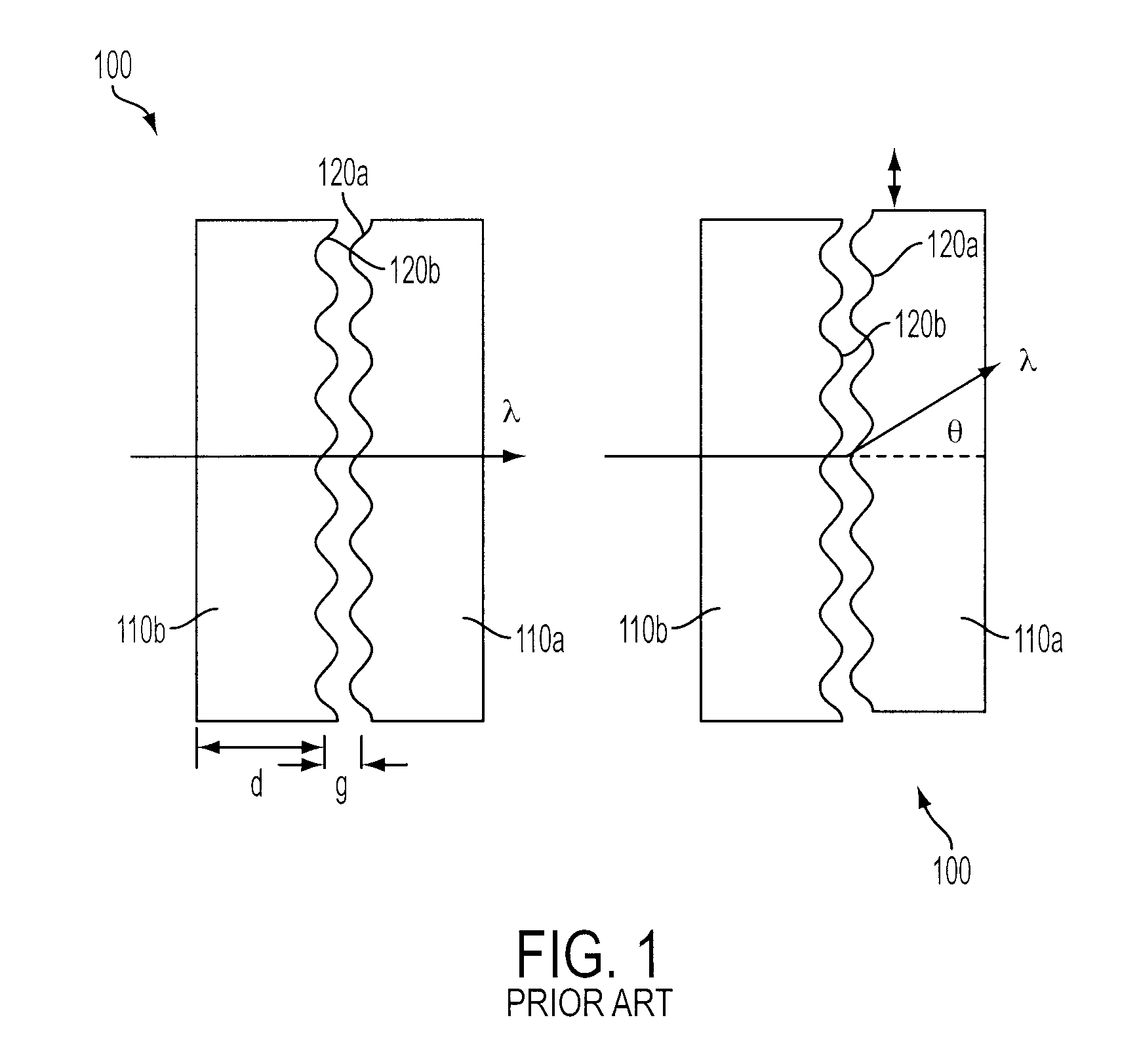
[0037]The benefits of the subject invention are shown in FIGS. 3a-3b, which compare a conventional diffractive phased array plate assembly 103 to an assembly 300 having membrane structures formed by a method in accordance with the subject invention. FIG. 3a illustrates a realistic case where the substrates 110a, 110b are slightly warped, demonstrating the difficulty in maintaining relatively small uniform plate spacing. For example, the plates could be in intimate contact at one location 2, while the gap between the plates could be tens of microns or larger at another location 1.

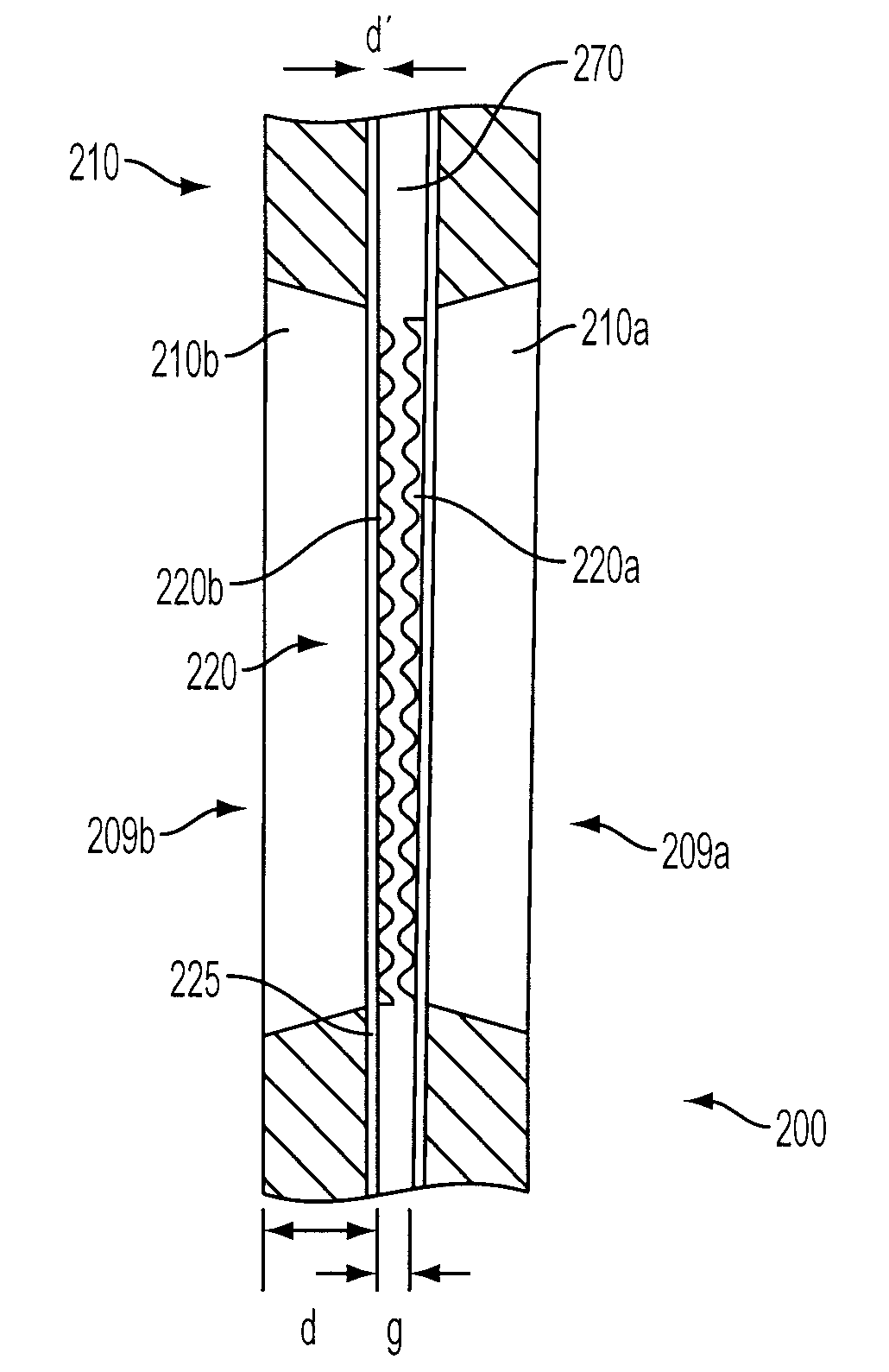
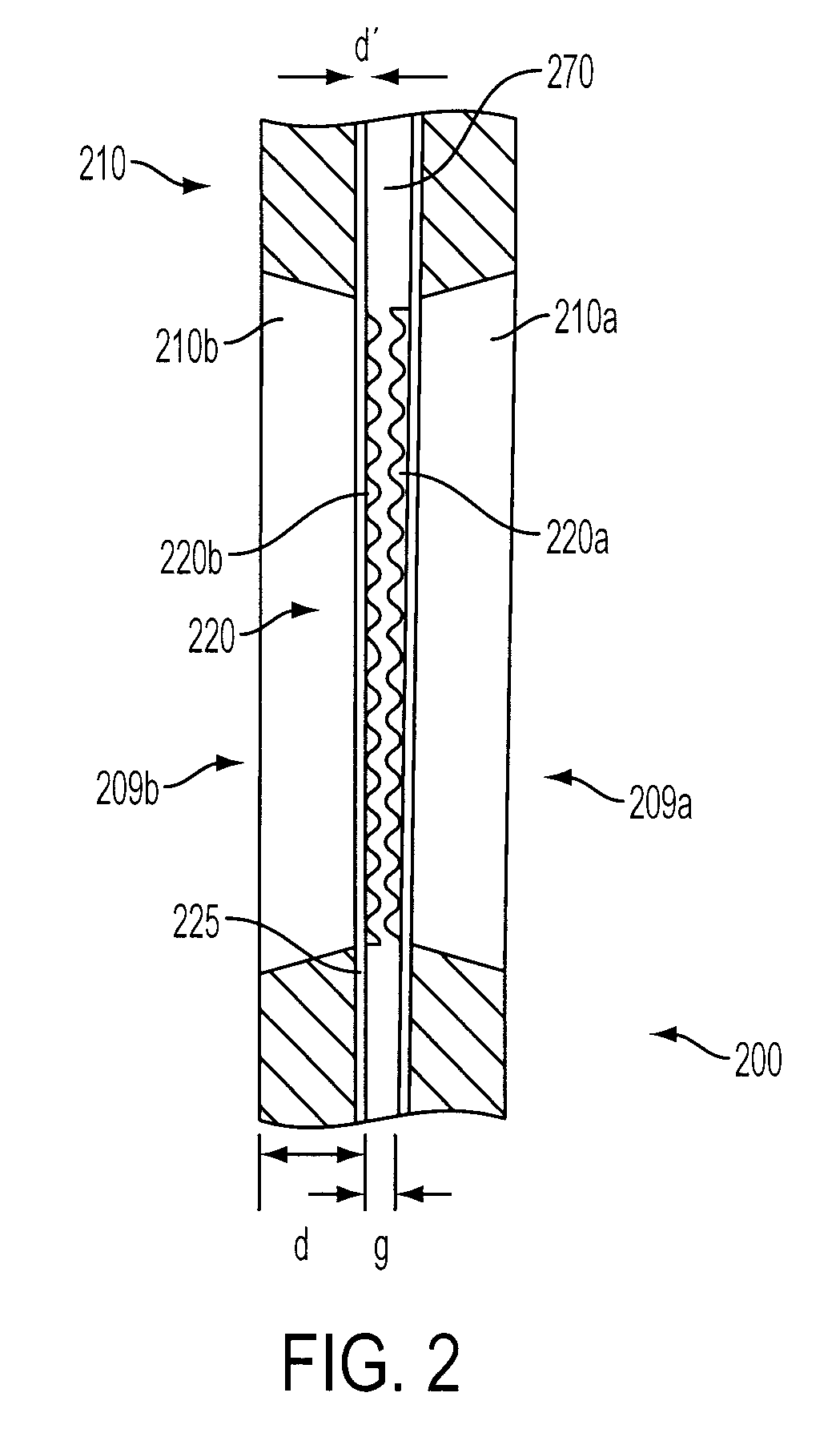
[0038]FIG. 3b illustrates how the two patterned gratings can be brought into operative uniform contact using a membrane grating approach. If the net strain of the combined structure is such that the thin film membrane layer 225 is pulled tightly across a window 209a, 209b formed in the substrate 210a, 210b, it will no longer exhibit the curvature of the substrate 210a, 210b. While this serves to reduce or el...


PUM


Abstract

A method of fabricating a membrane structure for a diffractive phased array assembly is provided. The method includes the steps of providing a wafer having a body and at least a membrane layer and a backside layer disposed on opposite faces of the body, forming a grating pattern on a surface of the membrane layer, and forming a window through the wafer to expose a back surface of the membrane, thereby allowing light to pass through the membrane.

Description

CROSS-REFERENCE TO RELATED APPLICATIONS[0001]This Application claims the benefit of priority of U.S. Provisional Patent Application No. 60 / 922,128, filed Apr. 6, 2007, which application is hereby incorporated by reference in its entirety.BACKGROUND[0002]1. Field of the Invention[0003]The subject invention is directed to a diffractive phased array assembly used as a beam steering device in an optical system, and to a method of fabricating and constructing such an assembly.[0004]2. Description of Related Art[0005]Diffractive phased array assemblies are used as beam steering devices in many optical systems such as bar code scanners, laser machining applications and laser printers, as discussed in U.S. Pat. No. 6,480,334 to Farn, the disclosure of which is herein incorporated by reference in its entirety.[0006]A known diffractive phased array design used as a beam steering device in LIDAR (Laser Imaging Detection and Ranging) applications is formed from 2-inch square silicon plates. The...

Claims


Application Information

Patent Timeline
IPC IPC(8): G02B27/44B29D11/00
CPCG02B5/1857G02B5/1871G02B27/4277G02B27/0087G02B26/0808
Inventor NESNIDAL, MICHAEL P.
Owner ROSEMOUNT AEROSPACE
Why Eureka
Try Eureka