Combined type flat plate compounding machine

A compound machine and combined technology, which is applied in the direction of layered products, lamination devices, lamination, etc., can solve the problems of large heat loss, troublesome processing, and large machine volume, so as to meet production needs, wide application range, and good quality. Strong bonding effect

Inactive Publication Date: 2015-04-01
JIANGSU HONGYE MACHINERY
View PDF6 Cites 16 Cited by
  • Summary
  • Abstract
  • Description
  • Claims
  • Application Information

AI Technical Summary

Problems solved by technology

At present, there are only simple single-chip heating and cooling models in China, which cannot meet special process requirements
For the compounding of two-layer, three-layer or more than three-layer materials, at present, glue is used to repeat multiple processes on a roller-heated compound machine for compounding, especially for some sheet materials, small batches, and upper and lower layer compounding. The processing of high-quality materials is very troublesome. Not only is the machine bulky and the heat loss is large, but also the fastness of the upper and lower composite layers of the material is different, which greatly affects the composite quality. The gap cannot be adjusted, which has great limitations for thicker and thinner composite materials, and cannot meet the production needs of enterprises

Method used


Image

  • Combined type flat plate compounding machine

Examples


Embodiment Construction

[0009] The specific content of the present invention will be described in detail below in conjunction with the accompanying drawings and specific embodiments.

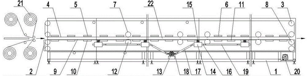
[0010] Such as figure 1 As shown, the combined flat-panel composite machine includes: a frame 1 and a support frame 2, on the frame 1, an upper conveyor belt 4 is provided through several upper pulleys 3, and the machine on the inner side of the lower end of the upper conveyor belt 4 The front end of the frame 1 is provided with some upper heating plates 5, and the rear end of the frame 1 inside the lower end of the upper conveyor belt 4 is provided with some upper cooling plates 6, and the frame 1 inside the lower end of the upper conveyor belt 4 is also provided with There are some upper pressure rollers 7, and a lower conveyor belt 9 is arranged on the support frame 2 through several lower pulleys 8, and a number of upper heating plates 5 are arranged on the front end of the support frame 2 on the inner side of the ...


PUM


Abstract

The invention discloses a combined type flat plate compounding machine. The combined type flat plate compounding machine comprises a rack and a supporting frame, wherein a plurality of upper heating plates are arranged at the front end of the rack at the inner side of the lower end of an upper conveyor belt, a plurality of upper cooling plates are arranged at the rear end of the rack at the inner side of the lower end of the upper conveyor belt; a plurality of lower heating plates which are matched with the upper heating plates are arranged at the front end of the supporting frame at the inner side of the upper end of a lower conveyor belt; a plurality of lower cooling plates which are matched with the upper cooling plates are arranged at the rear end of the supporting frame at the inner side of the upper end of the lower conveyor belt; a gap regulating mechanism comprises a speed reducer arranged at the lower end of the rack and a plurality of gearboxes arranged at the two sides of the speed reducer, wherein the lower end of a regulating screw is connected to the gearboxes, the upper end of the regulating screw is connected to the supporting frame, rotary shafts of the two gearboxes close to the two sides of the speed reducer are respectively connected to motor shafts at the two ends of the speed reducer by virtue of a first universal shaft, and the rotary shafts of the two gearboxes adjacent to the two sides of the speed reducer are connected with each other by virtue of a second universal shaft.

Description

technical field [0001] The invention relates to a composite device, in particular to a combined flat composite machine. Background technique [0002] GMT is a composite material with thermoplastic resin as the matrix and glass fiber felt as the reinforced skeleton. It needs to be heated for a long time and multi-layer hot pressing to form. Generally, semi-finished sheets can be produced, and then directly processed into products of the required shape. It has good mechanical properties, short molding cycle, low production cost, good impact strength, no welds in the final product, and recyclability, which makes it attract great attention from the automotive industry. Now the European auto industry is increasingly inclined to use GMT, using it to produce front-end parts, seat shells, engine noise shields, bumpers, dashboard brackets and other components. At present, there are only simple single-chip heating and cooling models in China, which cannot meet special process requi...

Claims


Application Information

Patent Timeline
Patent Type & Authority Applications(China)
IPC IPC(8): B32B37/06B32B37/08B32B37/10
CPCB32B37/06B32B37/08B32B37/10
Inventor 徐汉东还伟海卞书祥马一梓张乃扣
Owner JIANGSU HONGYE MACHINERY
Why Eureka
Try Eureka