A collision gap self-coordinating device

A self-coordination and collision technology, applied in the direction of building types, buildings, building components, etc., can solve the problems of narrow vibration reduction frequency band, large mass of collision damper, noise pollution, etc., achieve self-adaptation of excitation intensity, reduce bad vibration, The effect of improving the vibration damping effect

Active Publication Date: 2020-08-18
TONGJI UNIV
View PDF5 Cites 0 Cited by
  • Summary
  • Abstract
  • Description
  • Claims
  • Application Information

AI Technical Summary

Problems solved by technology

Among them, the collision damper and the suspended mass pendulum damper are two common vibration reduction control devices, and many obvious defects have been found in practice tests: 1) The mass of the collision damper itself is too large, which has an adverse effect on the main structure; 2 ) There is a noise pollution problem during the collision process; 3) The single tuning function of the suspended mass pendulum damper lacks an energy dissipation mechanism; 4) The single tuning device has extremely high requirements on the accuracy of the control frequency, and the vibration reduction frequency band is narrow
[0004] At present, during the collision process, the collision gap cannot be adaptively adjusted, and the self-coordination function of the collision gap cannot be realized according to the size of the excitation load, so that the adverse vibration of the structure in the horizontal direction cannot be effectively reduced.

Method used


Image

  • A collision gap self-coordinating device
  • A collision gap self-coordinating device
  • A collision gap self-coordinating device

Examples


Embodiment

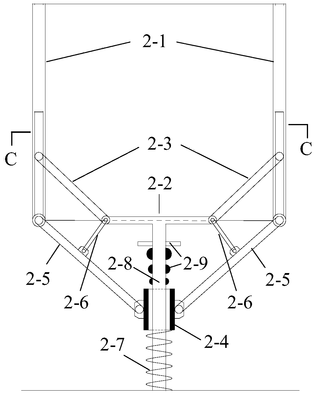
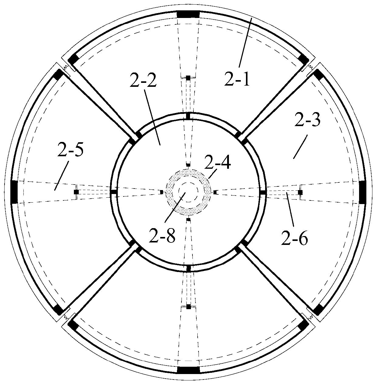
[0030] A collision gap self-coordination device, such as figure 1 , 2 As shown, it consists of a limit plate 2-1, a fixed chassis 2-2, a fan-shaped movable edge plate 2-3, a reset slider 2-4, a support member 2-5, a conversion rod 2-6, and a return spring 2-7 , Composed of fixed rods 2-8 and blocking members 2-9.

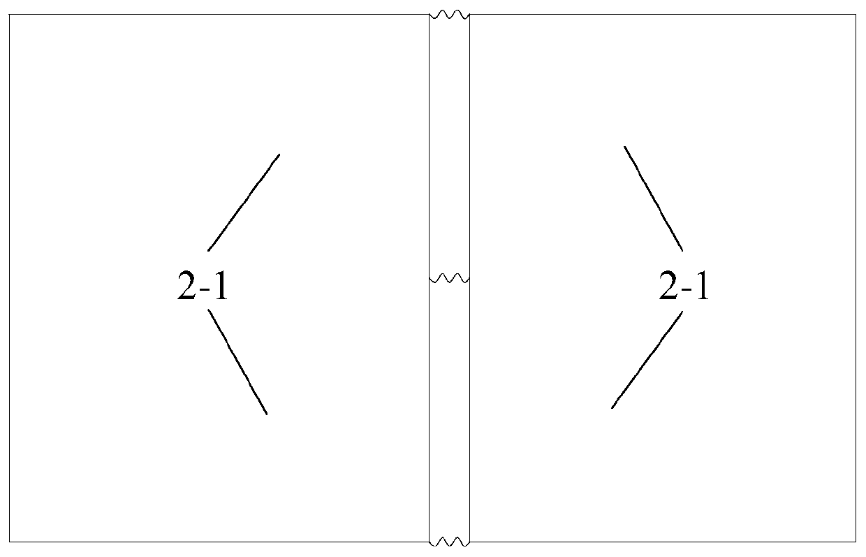
[0031] The limit plate 2-1 encloses the collision area, and the limit plate 2-1 is an arc-shaped vertical plate. In this embodiment, four limit plates 2-1 are arranged to enclose a cylindrical structure, such as image 3 , The two adjacent limit plates 2-1 are softly connected by three upper, middle and lower springs. The lower end of each limit plate is connected to the reset slider 2-4 through the support member 2-5, and the reset slider 2- 4 Nested on the fixed rod 2-8, the lower end is provided with a return spring 2-7, the upper part of the fixed rod is provided with a blocking member 2-9, the support member 2-5 is provided with a steering plate in the middle posi...


PUM


Abstract

The invention relates to a collision gap self-coordination device. The collision gap self-coordination device comprises a fixed chassis, a fixed rod part, a reset sliding block, multiple limiting plates, and multiple movable edge plates; the upper end of the fixed rod part is fixed to the lower end of the fixed chassis, a reset spring is arranged on the fixed rod part, the reset sliding block is arranged on the fixed rod part in a sleeving manner and is connected to the upper portion of the reset spring, a collision cavity is defined by the limiting plates, the fixed chassis is located on thebottom of the collision cavity, the lower ends of the limiting plates are hinged to one ends of multiple supporting parts, the other ends of the supporting parts are hinged to the reset sliding block,one ends of the movable edge plates are in sliding connection to the limiting plates, and the other ends of the movable edge plates are hinged to the fixed chassis. The self adjusting of the optimalcollision gap of a damper under different motivations can be achieved, the motivation strength self adaptation is achieved, a vibration reducing frequency band is wide, robustness is achieved, according to the magnitude of the exciting loads, the collision gap self-adaptation adjusting is achieved, poor vibration of the structure in the horizontal direction is reduced, and the vibration reducing effect is greatly improved.

Description

Technical field [0001] The invention belongs to the field of civil engineering structure vibration control, and specifically relates to a collision gap self-coordination device. Background technique [0002] With the rapid development of the social economy, the size of the building structure is increasing, from high-rise buildings to super high-rise buildings. At the same time, the threats to high-rise buildings such as earthquakes and wind loads are increasing day by day. In recent years, in previous major earthquakes and wind disasters, accidents of structural collapse and damage have occurred from time to time, and economic losses are incalculable. Therefore, the development and application of structural vibration reduction technology is an inevitable trend. [0003] Passive control technology has the characteristics of maturity, high cost performance, high reliability and easy maintenance, and is widely used in structural vibration reduction. Among them, the collision damper...

Claims


Application Information

Patent Timeline
Patent Type & Authority Patents(China)
IPC IPC(8): E04B1/98E04H9/02
CPCE04H9/023
Inventor 鲁正荣坤杰汪晏
Owner TONGJI UNIV
Why Eureka
Try Eureka