Suction muffler for compressors, compressor with the suction muffler, and apparatus having refrigerant circulation circuit including the compressor

a compressor and suction muffler technology, which is applied in the direction of liquid fuel engines, combustion air/fuel air treatment, positive displacement liquid engines, etc., can solve the problems of poor compression efficiency relative to the volume of refrigerant, noise generation, poor compression efficiency, etc., and achieve the effect of reducing suction noise and maximizing the amount of refrigerant sucked

Inactive Publication Date: 2006-05-30
SAMSUNG GWANGJU ELECTRONICS CO LTD
View PDF6 Cites 14 Cited by
  • Summary
  • Abstract
  • Description
  • Claims
  • Application Information

AI Technical Summary

Benefits of technology

[0014]Accordingly, it is an aspect of the present invention to provide a suction muffler, which is designed to maximize an amount of a refrigerant sucked into a compression chamber and reduce suction noise to the minimum when the refrigerant is sucked into the compression chamber, and provides a compressor with the suction muffler and an apparatus having a refrigerant circulation circuit including the compressor.

Problems solved by technology

When the exhaust stroke switches to the suction stroke in such a state, the refrigerant sucked into the compression chamber has small density relative to a volume thereof, so compression efficiency is poor.
Therefore, the compression efficiency is poor relative to the volume of the refrigerant which is sucked into the compression chamber.
In case of sucking or discharging the refrigerant into or from the compression chamber, an intake valve plate of the valve unit is opened or closed several thousand times per minute, so noise is generated due to mechanical friction.

Method used


Image

  • Suction muffler for compressors, compressor with the suction muffler, and apparatus having refrigerant circulation circuit including the compressor
  • Suction muffler for compressors, compressor with the suction muffler, and apparatus having refrigerant circulation circuit including the compressor
  • Suction muffler for compressors, compressor with the suction muffler, and apparatus having refrigerant circulation circuit including the compressor

Examples


Embodiment Construction

[0047]Reference will now be made in detail to the present preferred embodiments of the present invention, examples of which are illustrated in the accompanying drawings, wherein like reference numerals refer to like elements throughout.

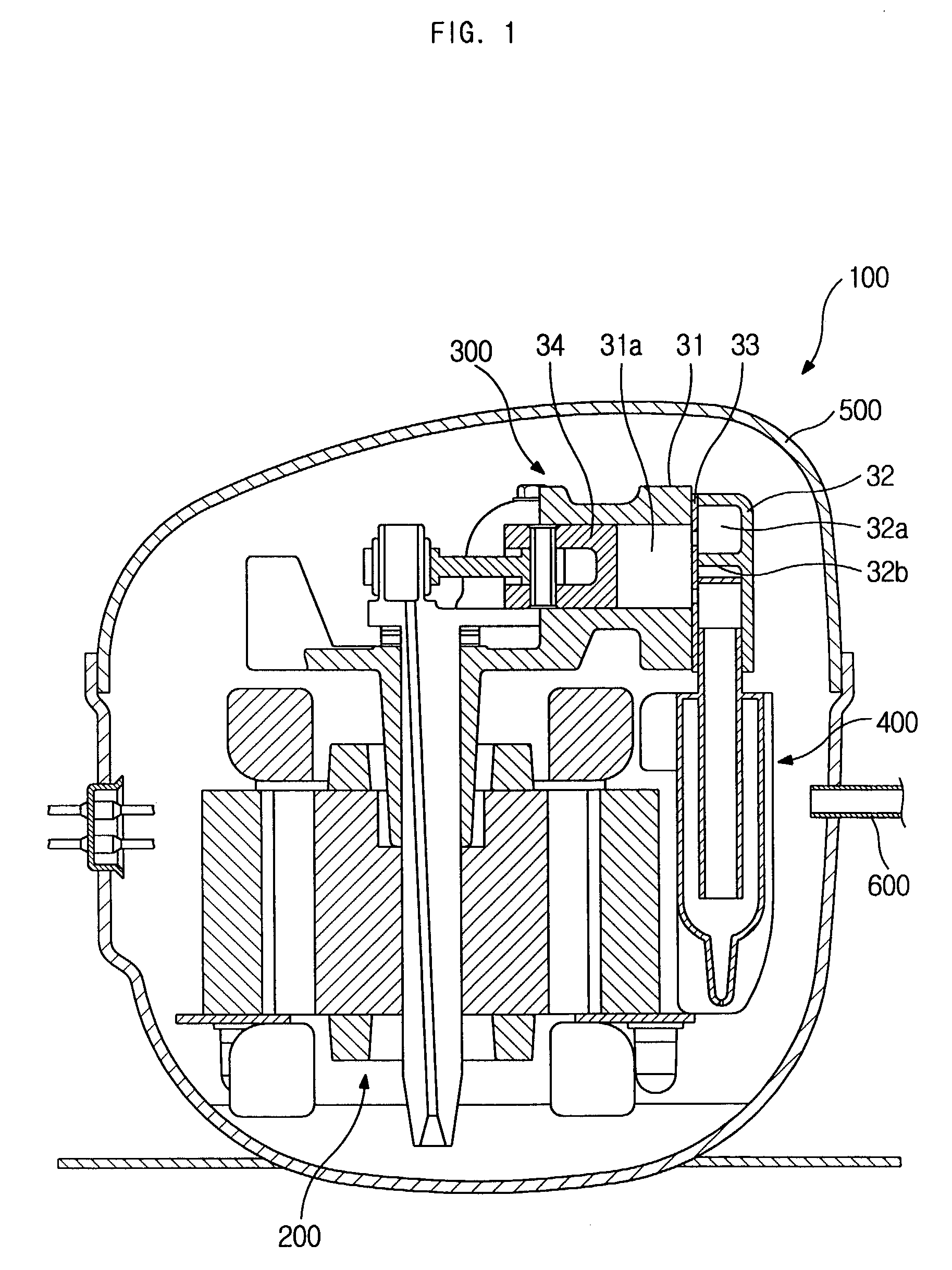
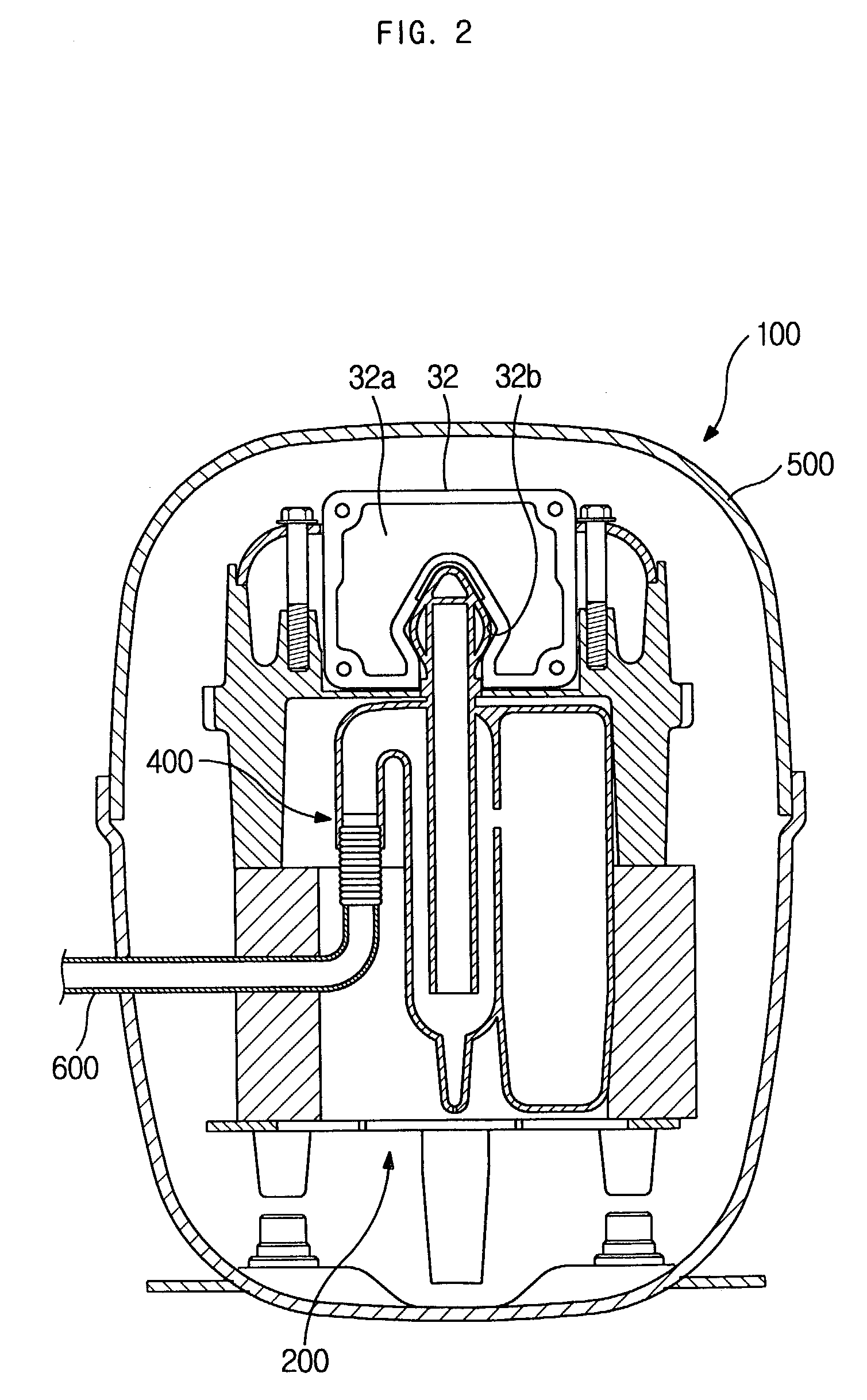
[0048]FIG. 1 is a side sectional view of a compressor, according to an embodiment of the present invention. FIG. 2 is a front sectional view of the compressor of FIG. 1.

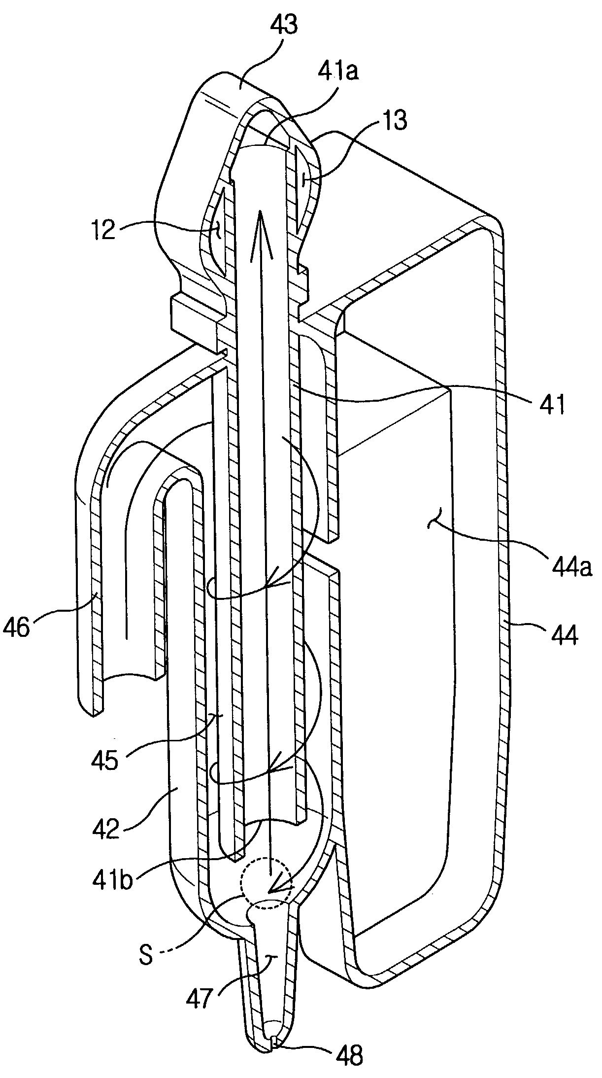
[0049]Referring to FIGS. 1 and 2, the compressor 100 according to an embodiment of the present invention includes a motor unit 200, a compressing unit 300, a suction muffler 400, a casing 500, a suction pipe 600, and an exhaust pipe (not shown). The motor unit 200 is provided at a lower portion of the compressor 100, and the compressing unit 300 is provided at a predetermined portion above the motor unit 200. The motor unit 200, the compressing unit 300, and the suction muffler 400 are hermetically sealed in the casing 500. The suction pipe 600 guides a refrigerant from an outside to t...


PUM


Abstract

Disclosed herein are a suction muffler for compressors, a compressor with the suction muffler, and an apparatus having a refrigerant circulation circuit including the compressor. The present invention allows an amount of a refrigerant sucked into a compression chamber to be maximized, and allows suction noise generated during a suction stroke to be minimized. The suction muffler includes a refrigerant channel, and an outer casing. The refrigerant channel communicates at an inlet thereof with a suction pipe which guides a refrigerant to a compressor, and controllably communicates at an outlet thereof with a compression chamber in which the refrigerant is compressed. The outer casing has a structure to convert a flowing motion of the refrigerant into a spiral flowing motion while the refrigerant flows from the suction pipe to the inlet. At least one resonance chamber is formed around an outlet of the refrigerant channel. The compressor having the suction muffler includes at least one insulating space to prevent a heat transfer between the refrigerant inside a refrigerant intake chamber and the refrigerant inside a refrigerant discharge chamber. Further, the compressor is applied to an apparatus having a refrigerant circulation circuit. The present invention increases compression efficiency of the compressor, and considerably reduces suction noise.

Description

CROSS-REFERENCE TO RELATED APPLICATION[0001]This application claims the benefit of Korean Application No. 2003-15341, filed Mar. 12, 2003, in the Korean Intellectual Property Office, the disclosure of which is incorporated herein by reference.BACKGROUND OF THE INVENTION[0002]1. Field of the Invention[0003]The present invention relates, in general, to a suction muffler for compressors, a compressor with the suction muffler, and an apparatus having a refrigerant circulation circuit including the compressor, more particularly, to a suction muffler which is designed to increase compression efficiency and reduce noise, a compressor with the suction muffler, and an apparatus having a refrigerant circulation circuit including the compressor.[0004]2. Description of the Related Art[0005]As well known to those skilled in the art, a refrigerant circulation circuit includes a compressor, a condenser, an expansion unit, and an evaporator. A refrigerant under low pressure is fed into the compress...

Claims


Application Information

Patent Timeline
Patent Type & Authority Patents(United States)
IPC IPC(8): F04B39/00F04B39/02F04B39/04
CPCF04B39/0061F04B39/00
Inventor LEE, SUNG TAE
Owner SAMSUNG GWANGJU ELECTRONICS CO LTD
Why Eureka
Try Eureka