
Air compressor

An air compressor, ambient air technology, used in mechanical equipment, machines/engines, liquid variable capacity machinery, etc.

Pending Publication Date: 2021-09-10
QINGDAO SRI TECH CO LTD
View PDF10 Cites 0 Cited by
  • Summary
  • Abstract
  • Description
  • Claims
  • Application Information

AI Technical Summary

Problems solved by technology

[0004] The embodiment of the present application provides an air compressor to at least solve the problem of lack of systematic design of oil-free lubricated air compressors in existing air compressors

Method used


Image

  • Air compressor
  • Air compressor
  • Air compressor

Examples


Embodiment 1

[0041] In order to make the purpose, technical solutions and advantages of the present application clearer, the present application will be described and illustrated below in conjunction with the accompanying drawings and embodiments. It should be understood that the specific embodiments described here are only used to explain the present application, and are not intended to limit the present application. Based on the embodiments provided in the present application, all other embodiments obtained by persons of ordinary skill in the art without creative efforts shall fall within the protection scope of the present application.

[0042] Obviously, the accompanying drawings in the following description are only some examples or embodiments of the present application, and those skilled in the art can also apply the present application to other similar scenarios. In addition, it can also be understood that although such development efforts may be complex and lengthy, for those of ...

Embodiment 2

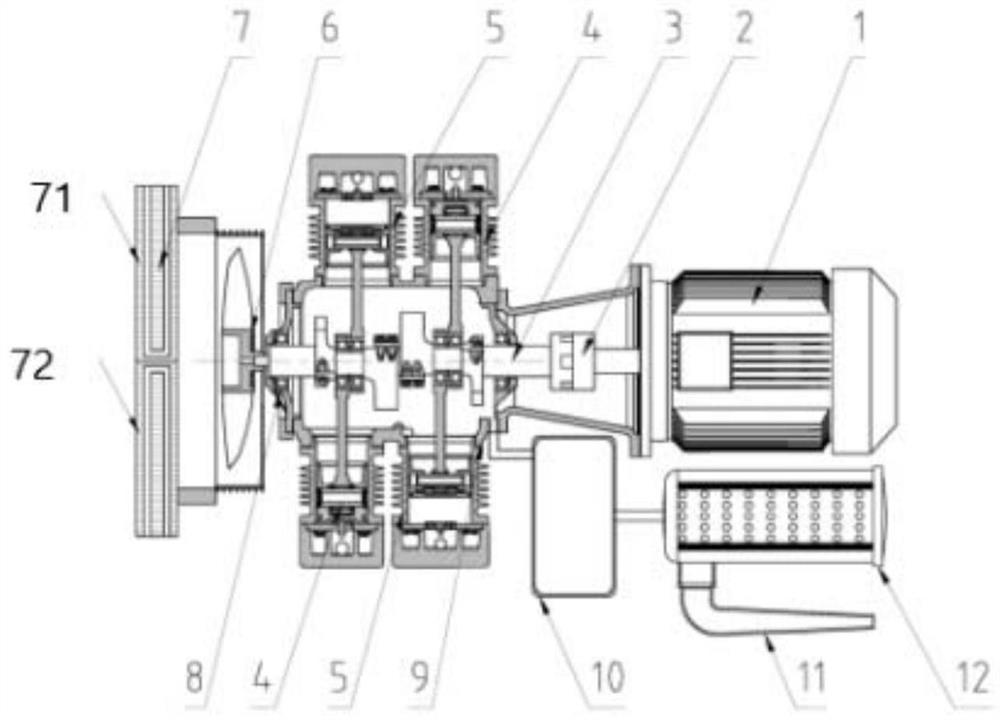
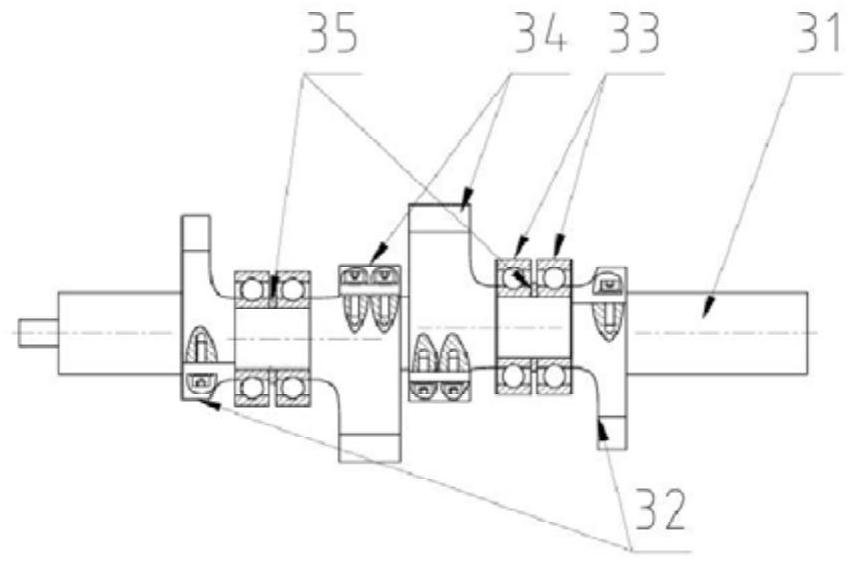
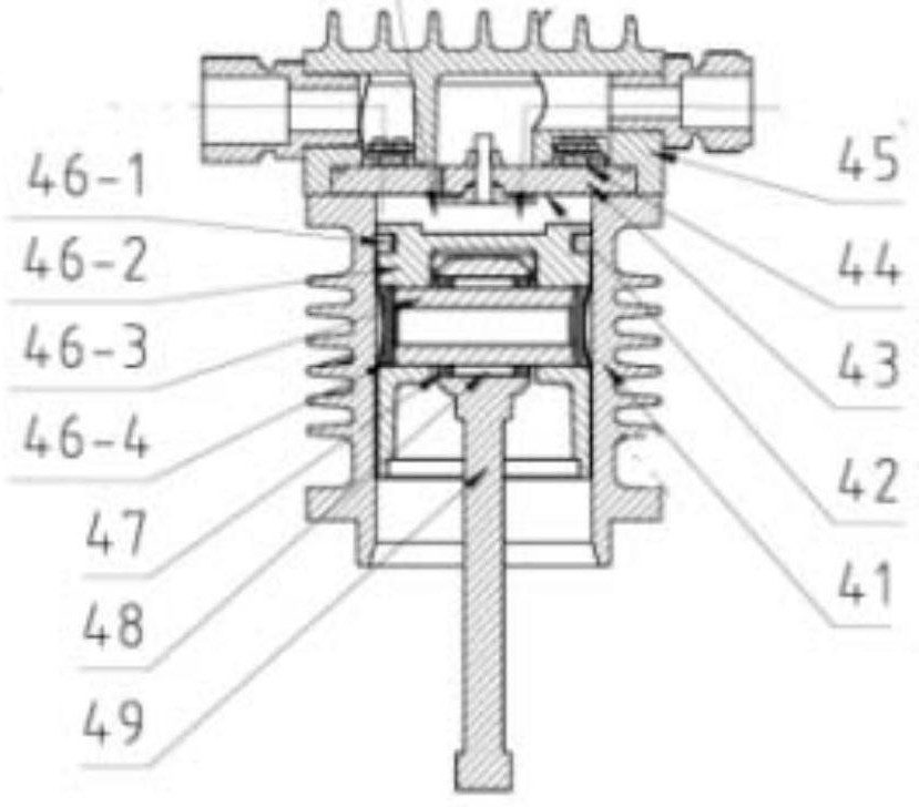
[0053] An air compression method using the above-mentioned air compressor: After the motor is started, the motor drives the crankshaft assembly to rotate through the elastic coupling. There are two turning grooves in the crankshaft, and the turning grooves drive the piston through the connecting rod during the eccentric movement Perform reciprocating motion. When the piston in the low-pressure cylinder assembly moves toward the center of the crankcase, the compressed air chamber of the low-pressure cylinder generates negative pressure, and the intake valve in the low-pressure cylinder assembly opens and the exhaust valve closes. After the intake valve is opened, the compressed air chamber of the low-pressure cylinder communicates with the crankcase, buffer chamber, and air filter. Under the action of atmospheric pressure, the air in the environment is filtered by the suction duct → air filter → buffer chamber → Crankcase → pipeline → is sucked into the compressed air chamber o...


PUM


Abstract

The invention discloses an air compressor. The air compressor comprises a crankcase, two high-pressure cylinder assemblies, two low-pressure cylinder assemblies and a motor, wherein a crankshaft assembly is arranged in the crankcase, the two high-pressure cylinder assemblies are correspondingly arranged on the two sides of the crankcase and connected to the crankshaft assembly, the two low-pressure cylinder assemblies are correspondingly arranged on the two sides of the crankcase and connected to the crankshaft assembly, the motor is connected to the crankshaft assembly through an elastic coupler, after the motor is started and drives the crankshaft assembly to rotate through the elastic coupler, sucked environment air is subjected to first-stage compression through the low-pressure cylinder assemblies, and the environment air subjected to first-stage compression enters an intercooler to be cooled, the high-pressure cylinder assemblies are used for carrying out second-stage compression on the environment air subjected to first-stage compression and cooling, the environment air subjected to second-stage compression enters an aftercooler to be cooled, and finally compressed air is output. According to the air compressor, a buffer chamber is arranged in front of the crankcase, so that the air suction buffer volume is further increased, and the air suction noise is reduced.

Description

technical field [0001] The invention belongs to the field of air compressors, and in particular relates to an air compressor. Background technique [0002] Compared with traditional oil-filled air compressors, oil-free air compressors have the advantages of environmental protection, less maintenance parts, high quality compressed air, and wide adaptability to working conditions. In recent years, with the development of oil-free lubricating material technology, rail vehicles at home and abroad have gradually begun to be equipped with oil-free air compressors. However, due to the late start of domestic related technologies, oil-free air compressors are still a "stuck neck" for China. "technology. [0003] In recent years, some domestic companies have successively carried out the research and development of oil-free piston air compressors for rail transit vehicles. However, during the test process, it was found that the developed prototypes had a series of problems such as hig...

Claims


Application Information

Patent Timeline
Patent Type & Authority Applications(China)
IPC IPC(8): F04B35/04F04B25/00F04B39/06F04B39/12F04B39/16F04B39/00
CPCF04B35/04F04B25/00F04B39/06F04B39/12F04B39/128F04B39/16F04B39/0005F04B39/0094F04B39/005
Inventor 吴学瑞郭宗斌郭凯江王令军秦东宾涂贵军张振超黄士伟张庆金
Owner QINGDAO SRI TECH CO LTD
Learn More