Method for depositing coatings on the interior surfaces of tubular structures

a tubular structure and interior surface technology, applied in the field of tubular structure coating, can solve the problems of becoming more and more difficult to deposit a substantially uniform coating over the entire interior surface, and most methods simply fail to achieve the effect of achieving uniformity

Inactive Publication Date: 2006-05-30
SOUTHWEST RES INST
View PDF12 Cites 85 Cited by
  • Summary
  • Abstract
  • Description
  • Claims
  • Application Information

AI Technical Summary

Benefits of technology

[0006]In one aspect of the application, a method of substantially uniformly coating an interior surface of a tubular structure (e.g., a ferromagnetic tube having a high aspect ratio) entails inducing a magnetic field of a given magnitude within the tubular structure. Further, a bias is applied at a given voltage to the tubular structure. Then, the interior surface of the tubular structure is exposed to a gaseous precursor material under conditions (e.g., voltage, pressure, bias frequency, etc.) effective to convert a quantity of the gaseous precursor material to ionize gaseous precursor material. The given magnitude and voltage is such that it is effective to deposit the ionized the gaseous precursor material onto the interior surface and converts the ionized gaseous precursor material to a substantially uniform protective coating in the interior surface.

Problems solved by technology

However, as the diameter of the tube becomes smaller and smaller, it becomes more and more difficult to deposit a substantially uniform coating over the entire interior surface.
Most methods simply do not succeed if the aspect ratio (length-to-diameter ratio) of the tube is high.

Method used


Image

  • Method for depositing coatings on the interior surfaces of tubular structures
  • Method for depositing coatings on the interior surfaces of tubular structures
  • Method for depositing coatings on the interior surfaces of tubular structures

Examples


example 1

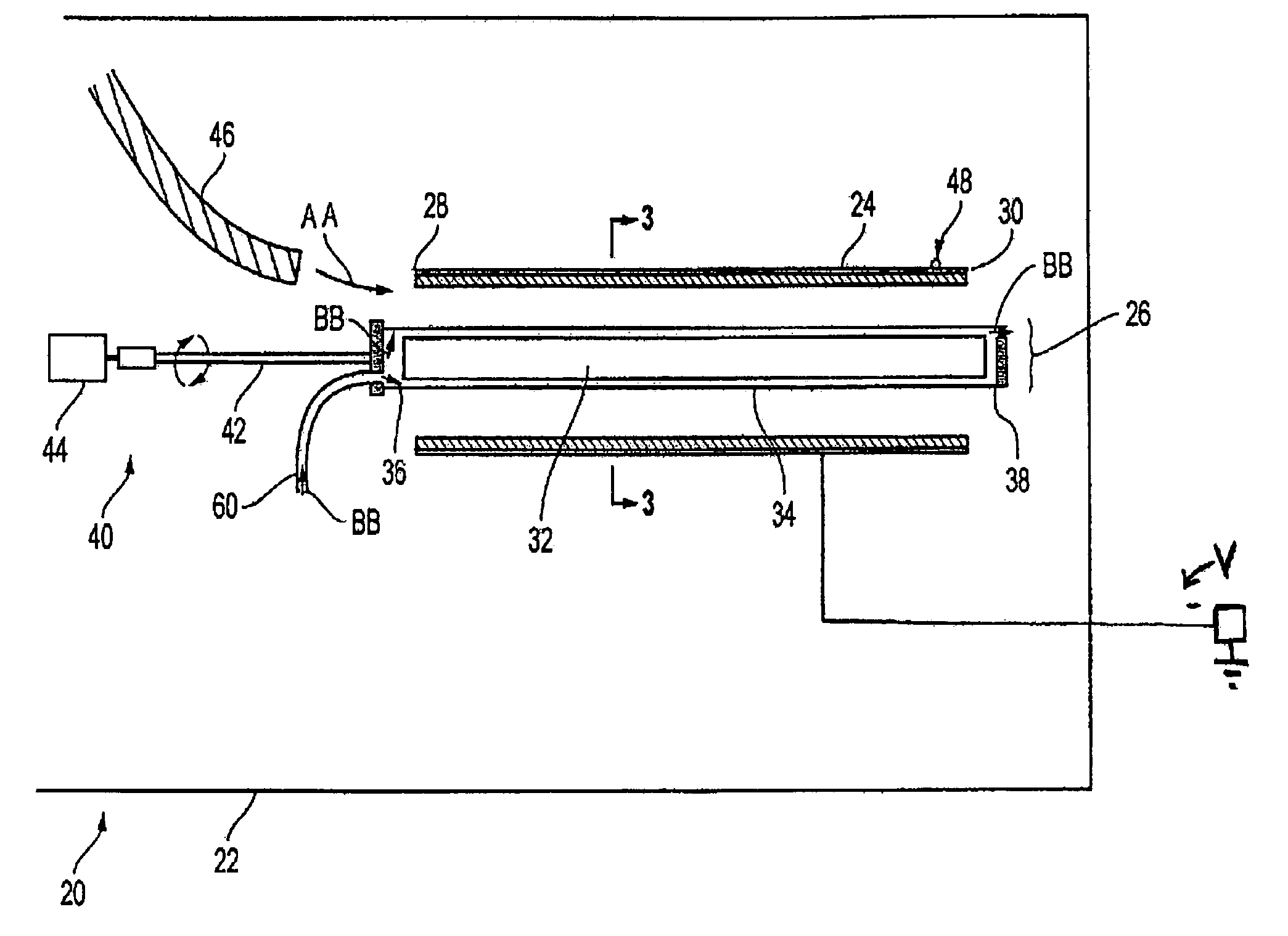
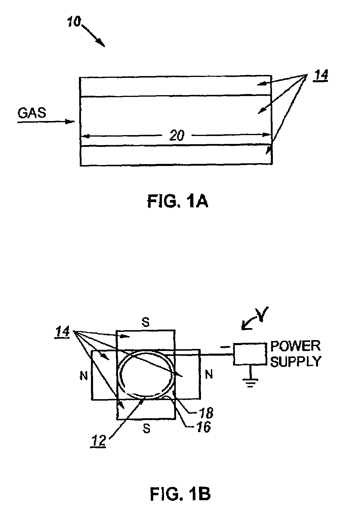
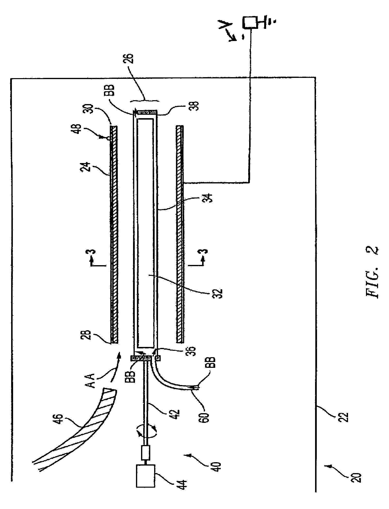
[0045]A non-ferromagnetic tube having a length of 16.2 cm and a diameter 1.27 cm (an aspect ratio of 12) was placed in a vacuum chamber. A magnetic assembly was placed lengthwise into the tube. The pressure in the vacuum chamber was pumped to 1.5×10⁻⁵ torr. A flow of 5 standard cubic centimeters per minute (SCCM) of argon was introduced to a pressure of 15 millitorr. A pulse frequency of 3 kHz with a pulse width of 20 microseconds was applied to bias the tube at 4 kV for about 30 minutes. The argon gas was turned off, and a combination of gases (SiH4, CH4, C2H2, N2 and Cr(CO)6) was introduced at 57 SCCM to obtain a pressure of 13 millitorr. A pulse frequency of 2 kHz at a pulse width of 20 microseconds was applied to bias the tube at 4 kV for about 30 minutes. The result was a well-bonded, substantially uniform + / −5–6 micrometer coating of silicon, silicon nitrides, silicon carbides, diamond-like carbon and carbonitrides covering the interior surface of the tube.

example 2

[0046]A ferromagnetic tube having a length of 17.1 cm and a diameter 1.9 cm (an aspect ratio of 37) was placed in a vacuum chamber. A magnetic assembly was placed lengthwise into the tube. The pressure in the vacuum chamber was pumped to 1.5×10⁻⁵ torr. A flow of 5 standard cubic centimeters per minute (SCCM) of argon was introduced to a pressure of 15 millitorr. A pulse frequency of 3 kHz with a pulse width of 20 microseconds was applied to bias the magnet assembly at 4 kV for about 30 minutes. The argon gas was turned off, and a combination of gases (SiH4, CH4, C2H2, N2 and Cr(CO)6) was introduced at 57 SCCM to obtain a pressure of 13 millitorr. A pulse frequency of 2 kHz at a pulse width of 20 microseconds was applied to bias the tube at 4 kV for about 30 minutes. The result was a well-bonded, substantially uniform + / −5–6 micrometer coating of silicon, silicon nitrides, silicon carbides, diamond-like carbon and carbonitrides covering the interior surface of the tube.


PUM

PropertyMeasurementUnit
vacuum pressureaaaaaaaaaa
aspect ratioaaaaaaaaaa

Abstract

A method is disclosed for substantially uniformly coating an interior surface of a ferromagnetic tubular structure such as a ferromagnetic tube having a high aspect ratio. The method entails inducing a magnetic field of a given magnitude within the tubular structure. Further, a bias is applied at a given voltage to the tubular structure. Then, the interior surface of the tubular structure is exposed to a gaseous precursor material under conditions effective to convert a quantity of the gaseous precursor material to ionize gaseous precursor material. The given magnitude and voltage is such that it is effective to deposit the ionized the gaseous precursor material onto the interior surface and converts the ionized gaseous precursor material to a substantially uniform protective coating in the interior surface.

Description

CROSS-REFERENCE TO RELATED APPLICATIONS[0001]This application is a continuation-in-part application of U.S. patent application Ser. No. 10 / 693,076, filed on Oct. 24, 2003 (now pending), which is a continuation-in-part of U.S. patent application Ser. No. 10 / 167,189, filed on Jun. 11, 2002 now U.S. Pat. No. 6,764,714.FIELD OF THE APPLICATION[0002]The present application relates to a method of coating a tubular structure, and more particularly, coating an inside surface of the tubular structure.BACKGROUND OF THE APPLICATION[0003]Deposition of coatings onto the interior surface of tubular structures is needed for various applications, including, but not necessarily limited to gun barrels, automotive cylinder bores, and tubes for special applications.[0004]Tubes with relatively large diameters have been successfully coated using known methods. However, as the diameter of the tube becomes smaller and smaller, it becomes more and more difficult to deposit a substantially uniform coating ov...

Claims


Application Information

Patent Timeline
Patent Type & Authority Patents(United States)
IPC IPC(8): B05D7/22C23C14/22B05D7/00B05D7/24
CPCB05D1/62B05D7/22F41A21/04Y10T428/13B05D2254/04B05D7/52
Inventor WEI, RONGHUARINCON, CHRISTOPHERARPS, JAMES
Owner SOUTHWEST RES INST
Why Eureka
Try Eureka