Electricity-feeding device

a technology of electric feed and wire harness, which is applied in the direction of insulating conductors, cables, and cable arrangements between relatively moving parts, etc., can solve the problems of reducing the durability of the wire harness, requiring installation cost and components cost of the reinforcing plate,

Inactive Publication Date: 2006-05-30
YAZAKI CORP
View PDF2 Cites 24 Cited by
  • Summary
  • Abstract
  • Description
  • Claims
  • Application Information

AI Technical Summary

Benefits of technology

[0022]According to the above, when the slider slides toward a bent part of the wire harness along the one wall, the wire harness is bent into a substantially loop shaped form having a large radius in between the one and the other walls. Further, when the slider slides in a direction opposite to the bent part of the wire harness along the one wall, the wire harness is bent into a substantially horizontally long half loop shaped form having a large radius in between the one and the other walls. In both cases, the wire harness led into the slider in the case is bent smoothly with a large radius, and arranged with a large radius from the other wall to the slider. The wire harness includes a first bent part with a large radius at the other wall side, and a second bent part with a small radius at the slider side. However, since an interval between both of the bent parts is large, a twist between both of the bent parts of the wire harness caused by the movement of the slider is reduced, and the durability of the wire harness against the repetitive twists is improved. The wire harness is bent with a small radius only in the slider in the case. Further, a whole body of the slider is accommodated in the case. Therefore, the slider is prevented from interfering with outer members, and the appearance of the electricity-feeding device is improved. Since the whole body of the slider is accommodated in the case, the electricity-feeding device is miniaturized.

Problems solved by technology

However, since the conventional electricity-feeding device 41 uses a flat wire harness as the wire harness 45, there is problems that such an electricity-feeding device requires the resilient reinforcing plate for regulating the slack of the wire harness 45, and requires installation cost and components cost of the reinforcing plate.
Resultingly, there is a problem that repetitive twists reduce durability of the wire harness 55.

Method used


Image

  • Electricity-feeding device
  • Electricity-feeding device
  • Electricity-feeding device

Examples


Embodiment Construction

Embodiment of the Present Invention

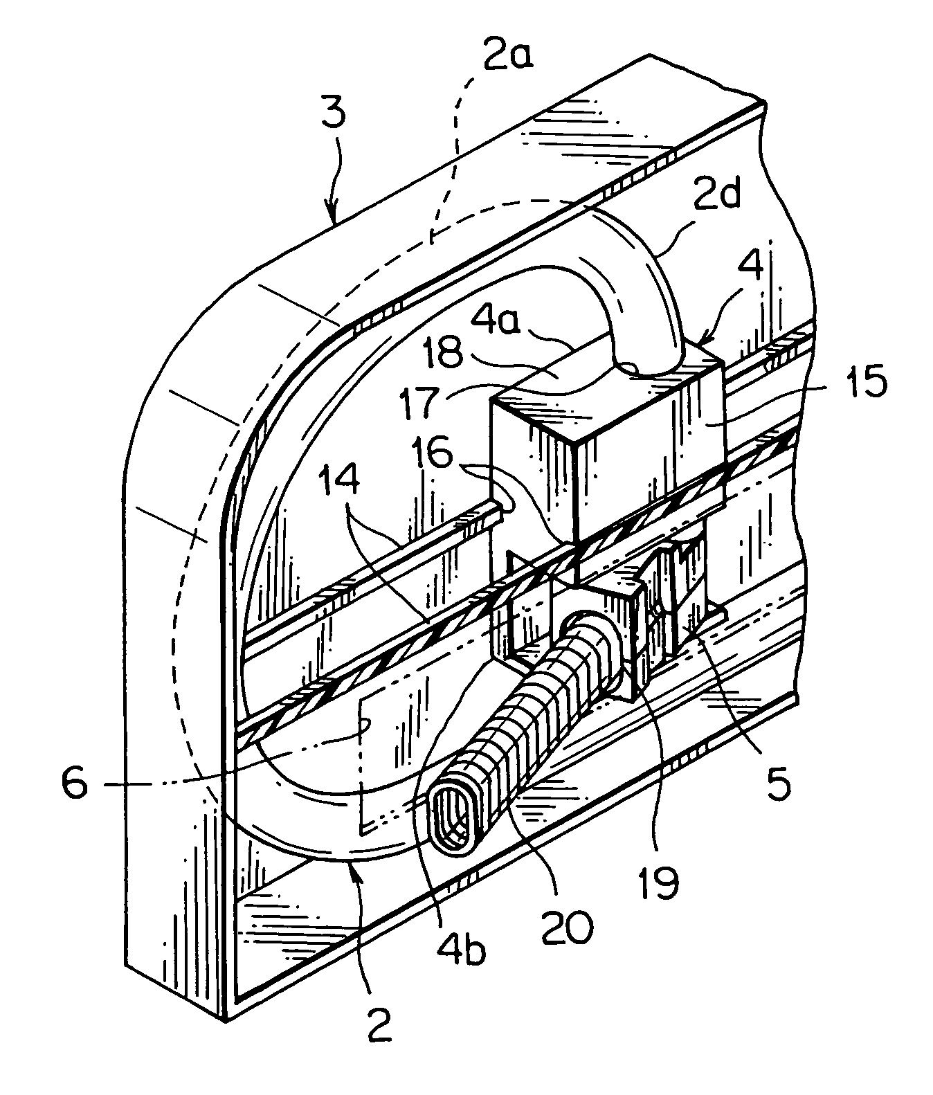
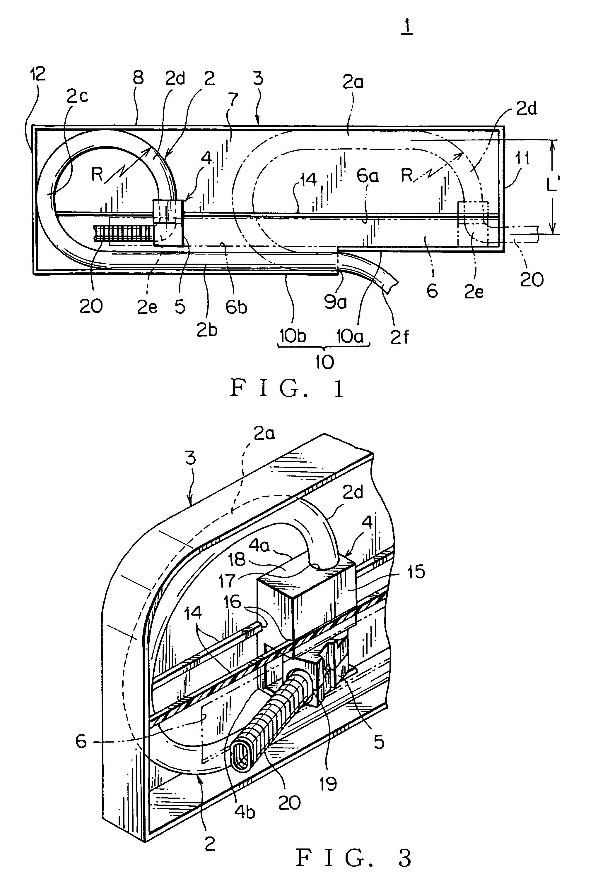
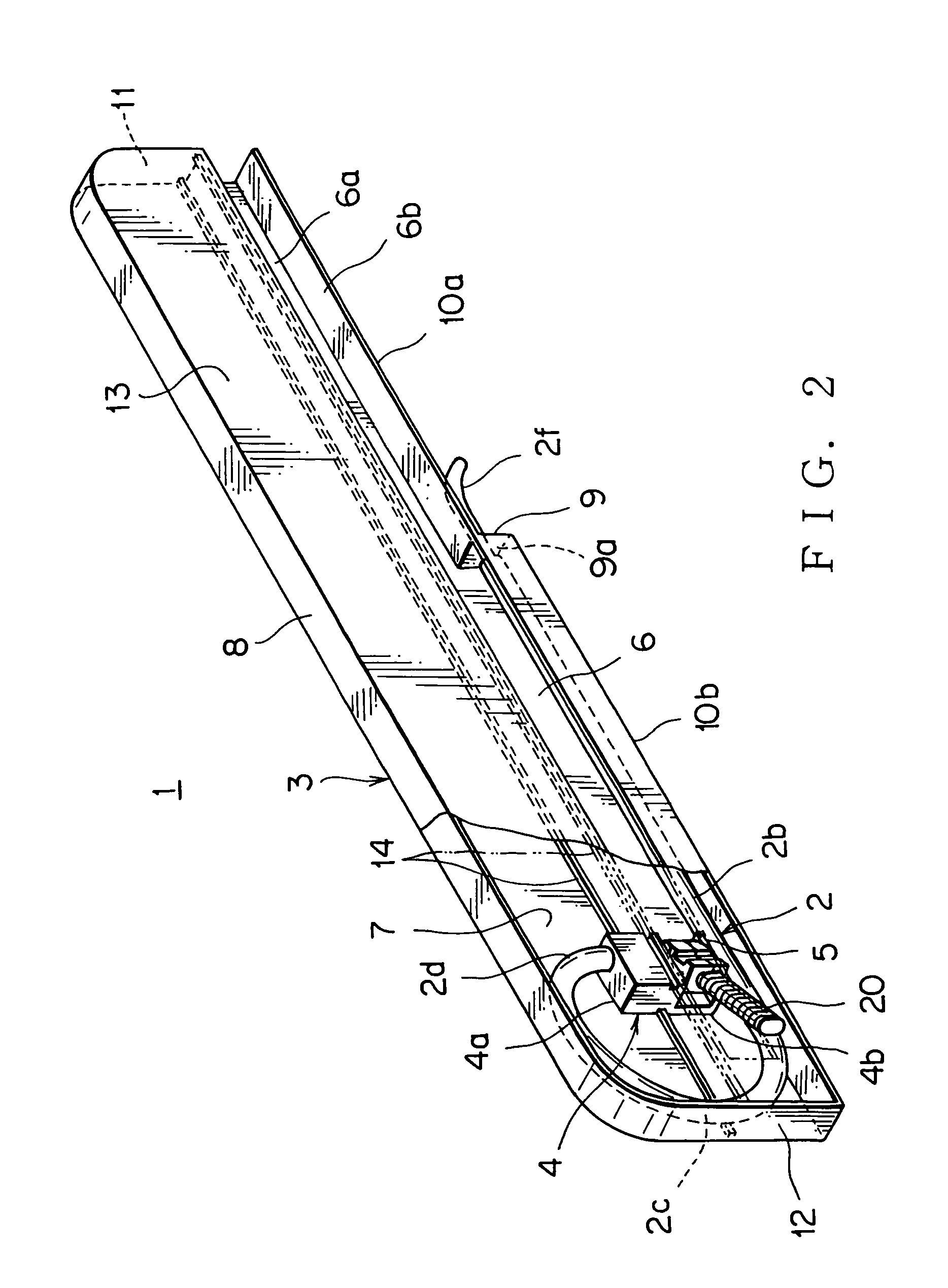
[0035]FIGS. 1 to 4 show an embodiment of an electricity-feeding device 1 according to the present invention. FIG. 1 shows a schematic view of the electricity-feeding device 1, and FIGS. 2 to 4 show configurations of the electricity-feeding device 1 of which slider is sliding.

[0036]The electricity-feeding device 1 includes a case 3 and a slider 4. The case 3 is made of synthetic resin in a substantially rectangular shaped form, and receives a wire harness bent into a substantially U-shaped form or a loop shaped form. The slider 4 is made of synthetic resin, engaged slidably with the case in between an upper part 2a and a lower part 2b of the wire harness 2, and bend the wire harness 2 into a substantially L-shaped form to lead out the wire harness 2 from the case 3 through a horizontally long opening 6 with a swinging member 5.

[0037]The case 3 includes: a base wall 7; an upper wall 8 (the other wall) being straight, horizontally long, and orthogonal...


PUM


Abstract

An electricity-feeding device includes: a case for accommodating a wire harness bent into a substantially U-shaped form; a slider slidable in the case, in which slider the wire harness is bent and through which the wire harness is led out swingably; and a horizontally long opening disposed between one and the other walls opposite to each other in the case. The slider slides along the opening. The wire harness is bent in traverse from the one wall to the other wall, then bent toward the one wall to be led into the slider, and then led out through the slider and the opening. A rail on which the slider is slidably guided is formed in the vicinity of the opening of the case. A swinging member is formed on the slider. The wire harness is bent and led out through the slider and the swinging member.

Description

BACKGROUND OF THE INVENTION[0001]The priority application claims priority of Japanese Patent Application No. 2004-230585, which is hereby incorporated by reference.FIELD OF THE INVENTION[0002]This invention relates to an electricity-feeding device, and in particular, the electricity-feeding device to reduce a torsional load to a wire harness that is bent into a substantially U-shaped form in a case and led out through a slider.DESCRIPTION OF THE RELATED ART[0003]FIG. 5 shows an embodiment of a conventional electricity feeding device disclosed in a document JP-A, H11-342807 (Page 4, FIGS. 1 and 2).[0004]In this document, an electricity-feeding device 41 is mounted on a sliding door 42 of a vehicle. A long sideways case 44 accommodates a flat wire harness 45 being bent into a substantially U-shaped form. A slider 46 is slidably mounted on the case 44. One end of the wire harness 45 is fixed on the slider 46, and the other end of the wire harness 45 is fixed on the case 44.[0005]The sl...

Claims


Application Information

Patent Timeline
Patent Type & Authority Patents(United States)
IPC IPC(8): H02G1/00
CPCB60R16/0215H02G11/006H02G11/00
Inventor TSUBAKI, AKIRAMATSUO, TATSUROIWASAKI, TAKAHIRO
Owner YAZAKI CORP
Why Eureka
Try Eureka