Eureka AIR delivers breakthrough ideas for toughest innovation challenges, trusted by R&D personnel around the world.

Pattern drawing method by scanning beam and pattern drawing apparatus

Inactive Publication Date: 2006-05-30
KONICA CORP
View PDF12 Cites 1 Cited by
  • Summary
  • Abstract
  • Description
  • Claims
  • Application Information

AI Technical Summary

Benefits of technology

[0052](3-5) An electronic beam drawing method according to (3-4), wherein it is drawn by adjusting the number of the scanning line which is drawn by the first dose amount and the number of the scanning line which is drawn by the second dose amount, so that the duty ratio of the concave part formation portion to one pitch of the concave convex part formation portion is decreased stepwise as the height of the inclination portion faces toward a side to be decreased.
[0053](3

Problems solved by technology

As a method for drawing processing such a material, there is a limitation in the conventional cutting processing or laser processing.
Further, as an another problem, when the diffractive ring-shaped zonal structure of the binary pattern or blaze shape, is approximated by a polygon and drawn, as compared to a case where the diffractive ring-shaped zonal structure of the binary pattern or blaze shape is formed by an ideal circular pattern drawing, the lowering of optical characteristic of the optical lens, particularly, lowering of the diffraction efficiency are caused, further, because the portion of the joint of the drawing line in the apex of the polygon is conspicuous, when the quality of the products is considered, there is a problem that the products value is lowered from its appearance.

Method used


Image

  • Pattern drawing method by scanning beam and pattern drawing apparatus
  • Pattern drawing method by scanning beam and pattern drawing apparatus
  • Pattern drawing method by scanning beam and pattern drawing apparatus

Examples


first embodiment

The First Embodiment

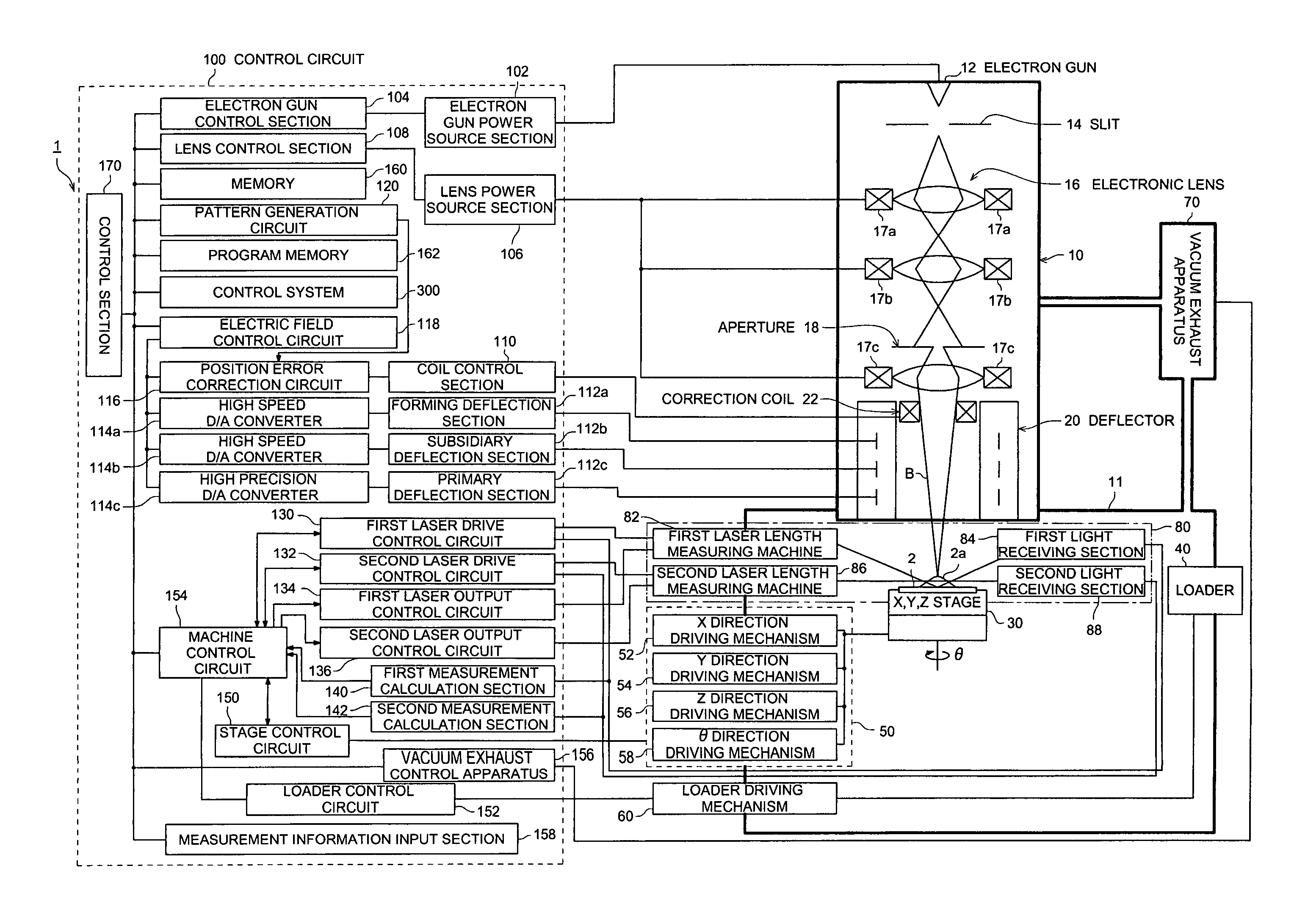
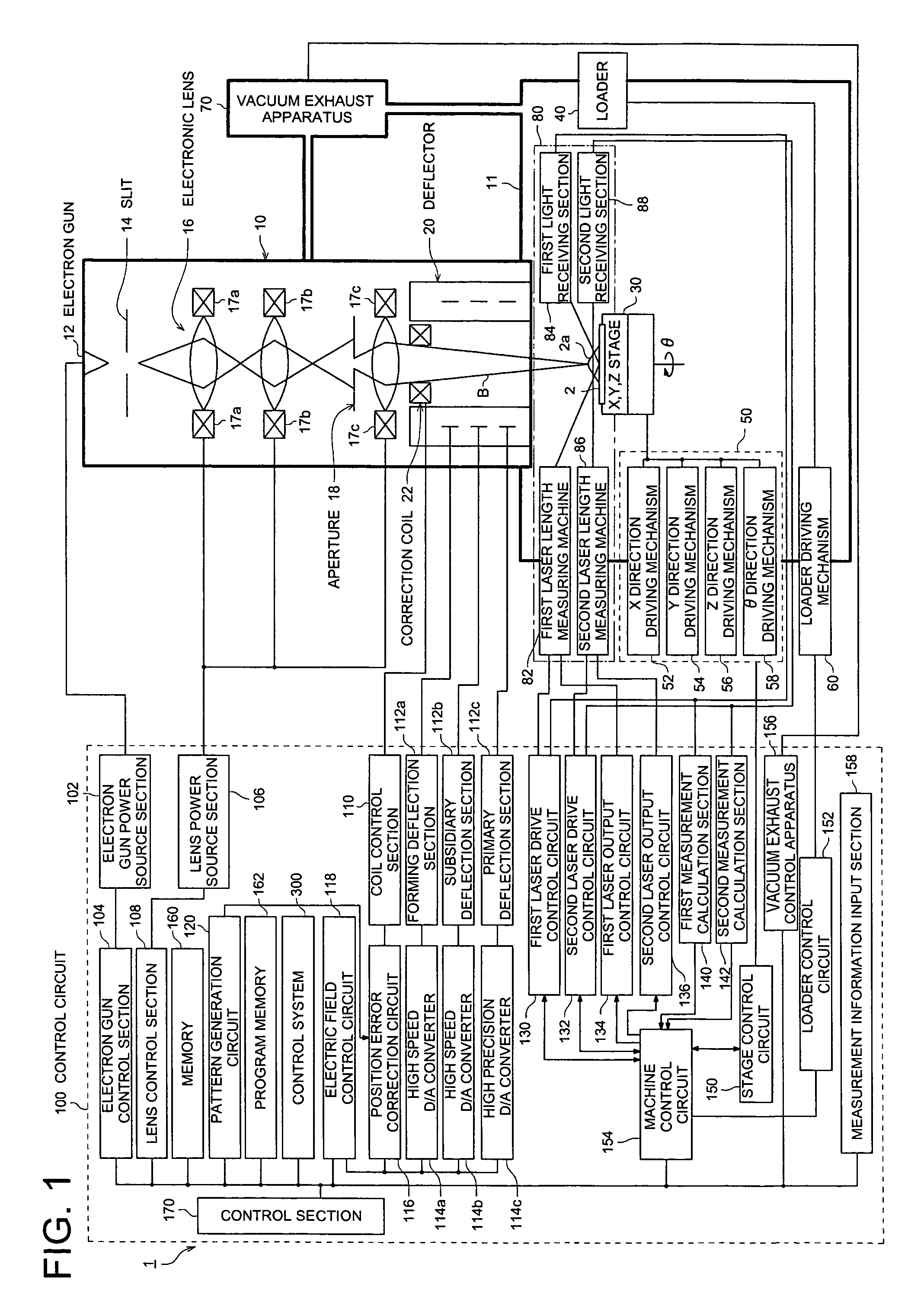
[0152]Initially, the present embodiment to attain the first object is characterized in that: when the electronic beam drawing is conducted in order to form the groove portion on one surface of the base material, particularly, in order to draw the inclined surface of the groove portion, when the dose distribution is changed, for example, from the first dose amount to the second dose amount, on a boundary portion of them, when the dose amount mixing area in which the first dose amount and the second dose amount are mixed, is provided, a gentle groove portion inclination portion in which the step difference due to the minimum dose resolving power of the electronic beam drawing apparatus which is determined by the minimum time resolving power of the D / A converter after the development processing, is suppressed, can be obtained.

[0153]Further, in the present embodiment, a case where the groove portion of the groove portion shape is formed while the circle drawing is co...

first example

THE FIRST EXAMPLE

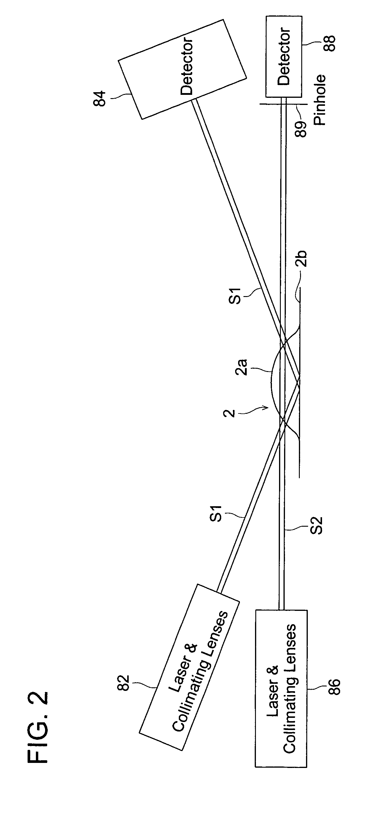
[0154]As shown in FIG. 10, the base material 2 has a curved surface portion 2a which is formed on at least one surface, and a groove portion 3 is inclined and formed every each pitch Ll, and a side wall portion 3a rising from the curved surface portion 2a at the division position of the pitch, an inclination portion 3b formed between the adjoining each of side wall portions 3a, 3a, and a valley portion 3c formed on a boundary area between the side wall portion 3a and the inclination portion 3b are formed.

[0155]In the inclination portion 3b, an inclination surface in which its one end contacts with a base end of the one hand side wall portion 3a, and the other end contacts with a tip of the other hand side wall portion 3a, is structured. Hereupon, these plurality of groove portions 3, as will be described later, are formed when the coating agent (resist) coated on the curved surface portion 2a is drawn by the electronic beam drawing apparatus and this is development ...

second example

THE SECOND EXAMPLE

[0233]Next, according to FIG. 26 and FIG. 27, the second example of the electronic beam drawing method, production method of the moldings, and electronic beam drawing apparatus according to the present invention, will be described. Hereupon, in the following, the explanation, relating to the practically same structure as the first example, will be omitted, and only the different part will be described.

[0234]In the first example, although a case where the dose amount division area which is stepwise in the sectional direction (inclination direction) of the inclination portion 3b of the groove portion 3, and the first scan section and the second scan section of the dose amount mix area are structured, is described with an example, in the present embodiment, a case where the first scan section and the second scan section of the dose amount mix area are formed in the scan direction of the electronic beam, will be described.

[0235]That is, the characteristic of the base m...


PUM


Abstract

A pattern drawing method of drawing a desired pattern on a base material by irradiating an electronic beam and scanning the base material with the electronic beam with a predetermined dose amount, comprising: a first step of drawing a first region on the base material by scanning with the electronic beam with a first dose amount; a second step of drawing a second region on the base material by scanning with the electronic beam with a second dose amount; and a inclining step of inclining a boundary between the first region and the second region to form an inclined surface by conducting a first scanning to scan with the electronic beam with the first dose amount and a second scanning to scan with the electronic beam with the second does amount in a mixed arrangement.

Description

BACKGROUND OF THE INVENTION[0001]The present invention relates to an electronic beam pattern drawing method, a production method of a molding die, a production method of moldings (molded product), and an electronic beam pattern drawing apparatus.[0002]Conventionally, as an information recording medium, for example, CDs and DVDs are widely used. Then, many optical elements are used for a precision equipment such as a reading apparatus for reading these recording media. There are many cases where, for optical elements used for these equipments, for example, optical lenses, from a viewpoint of the cost reduction and size reduction, resin optical lenses rather than glass optical lenses are used. Such a resin optical lens is produced by a general injection molding, and also the molding die for the injection molding is formed by a general cutting processing.[0003]In this connection, in the optical lenses, for example, an optical lens used for the reading apparatus having the interchangeab...

Claims


Application Information

Patent Timeline
IPC IPC(8): G21K5/10G02B3/08G03F7/22G11B7/135H01J37/302H01J37/304H01J37/317
CPCB82Y10/00B82Y40/00G02B5/1857G02B5/1876H01J37/3045H01J37/3174G11B7/13922H01J2237/31766H01J2237/30461H01J2237/31764
Inventor MASUDA, OSAMUFURUTA, KAZUMI
Owner KONICA CORP
Why Eureka
Eureka Blog
Learn More