Signal processing apparatus and signal processing method

a signal processing and signal processing technology, applied in the direction of two-way working systems, instruments, television conference systems, etc., can solve the problems of whitening process, loss of unique characteristics of codes from the received signals, and inability to estimate the direction or directions or the position or positions of a signal source or sources insufficient ways, etc., to achieve the effect of superior signal emphasis

Inactive Publication Date: 2006-05-30
SONY CORP
View PDF3 Cites 102 Cited by
  • Summary
  • Abstract
  • Description
  • Claims
  • Application Information

AI Technical Summary

Benefits of technology

[0051]In the signal processing apparatus and methods, a signal or signals from a signal source or a plurality of signal sources are received by a plurality of reception apparatus, and the received signals are decomposed into signals of different frequency bands by a plurality of band-pass filters. Then, cross correlation functions between the different frequency band signals originating from two different ones of the reception apparatus are calculated for individual combinations of the reception apparatus for the individual corresponding frequency bands. If the power of noise having no directivity is high in some of the frequency bands, then the cross correlation functions of the frequency band do not exhibit a maximum value, and therefore, an influence of the noise can be suppressed effectively when delay times of the individual reception apparatus which depend upon the direction or directions or the position or positions of the signal source or sources or upon the direction or directions or the position or positions of the signal source or sources and the arrangement of the reception apparatus are estimated.
[0060]According to the present invention, since received signals from a plurality of reception apparatus which receive a signal or signals from a signal source or a plurality of signal sources are decomposed into a plurality of different frequency band signals by a plurality of band-pass filters and cross correlation functions between the different frequency band signals are calculated for individual combinations of the reception apparatus for the individual corresponding frequency bands and then the direction or directions or the position or positions of the signal source or sources are estimated based on the cross correlation functions, even where significant noise is present or a plurality of signal sources generate signals at the same time, the direction or directions or the position or positions of the signal source or sources can be estimated sufficiently.

Problems solved by technology

The prior art apparatus and methods described above, however, cannot estimate the direction or directions or the position or positions of a signal source or sources sufficiently where significant noise is present or where a comparatively great number of signal sources generate signals at a time.
Meanwhile, where the method wherein the polarities of the signals after whitened are extracted is utilized, a unique characteristic to codes from the sound source included in the received signals is lost through the process of the whitening process.
Therefore, the cross correlation functions are influenced significantly by noise, and consequently, the estimation function of the sound source direction is deteriorated.
This method, however, is directed to noise of an aircraft measured in the proximity of an airfield.
According to the method, however, a great amount of calculation is required for logarithmic calculation for the frequency bands of the input signals from the microphones, and hardware of a large scale is required to perform such calculation.
Further, where the power of a signal is comparatively low or where the power of noise is comparatively high, it is sometimes impossible to reduce the influence of reflected sound through the logarithmic processing.
Further, since the emphasis signal is obtained by delaying a signal prior to decomposition into signals of different frequency bands as it is, if comparatively high noise is included in a certain frequency band, then the noise cannot be suppressed sufficiently.
However, the minimum variance method is one of methods which can be applied where the number of sound sources is smaller than the total number of microphones included in the microphone array, and involves a great amount of calculation.
If a delay sum method is used in place of the minimum variance method, then the amount of calculation can be reduced by a certain amount, but this deteriorates the estimation accuracy of the sound source position or direction.
In summary, with the prior art apparatus and methods described above, where the direction or the position of a signal source is not known in advance and much noise is present or a comparatively great number of signal sources generate signals at a time and particularly the number of signal sources is greater than the number of reception apparatus, the direction or directions or the position or positions of one signal source or a plurality of signal sources cannot be estimated with a sufficient degree of accuracy, and a signal or signals from one signal source or a plurality of signal sources cannot be emphasized sufficiently.

Method used


Image

  • Signal processing apparatus and signal processing method
  • Signal processing apparatus and signal processing method
  • Signal processing apparatus and signal processing method

Examples


first embodiment

[First Embodiment]

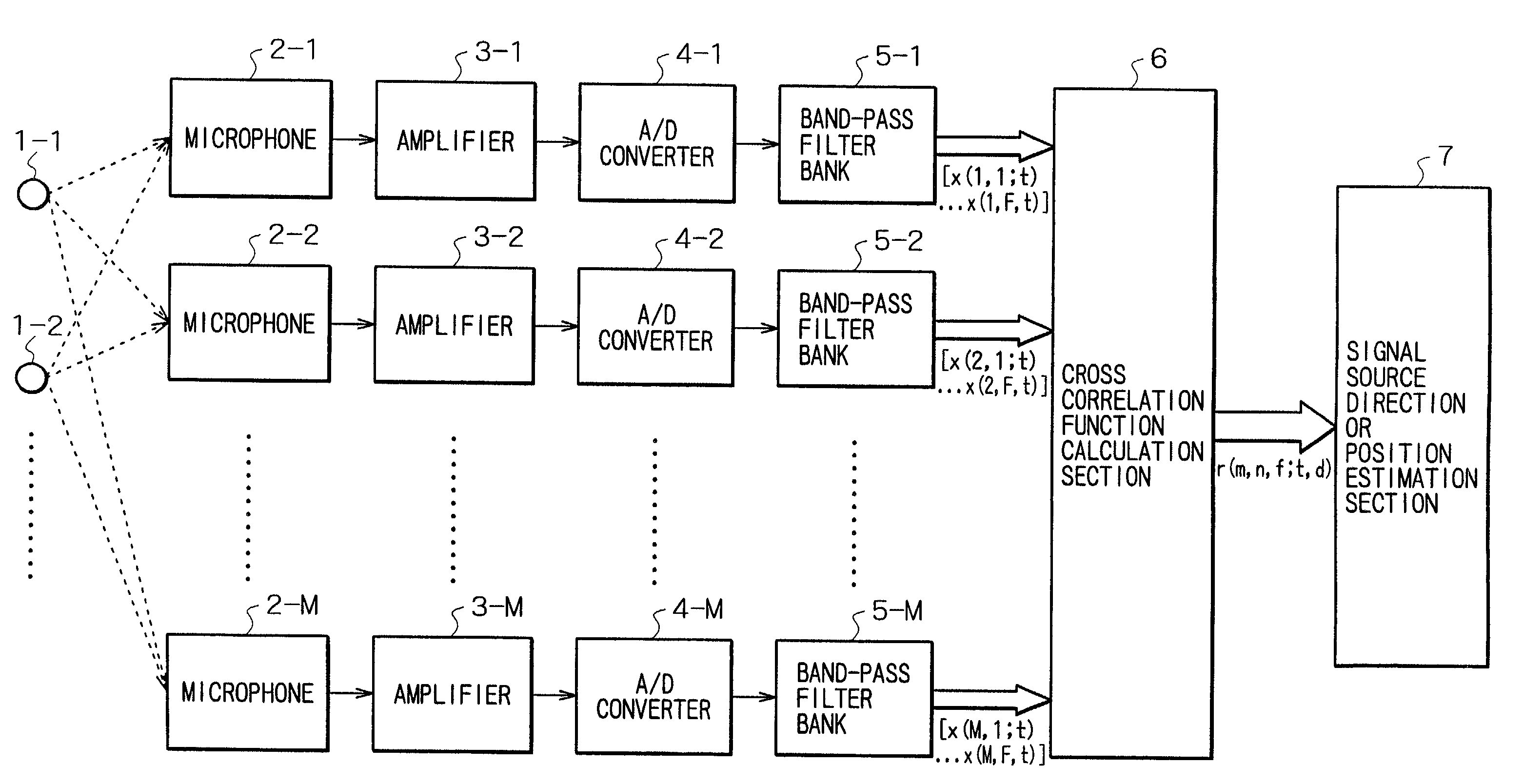
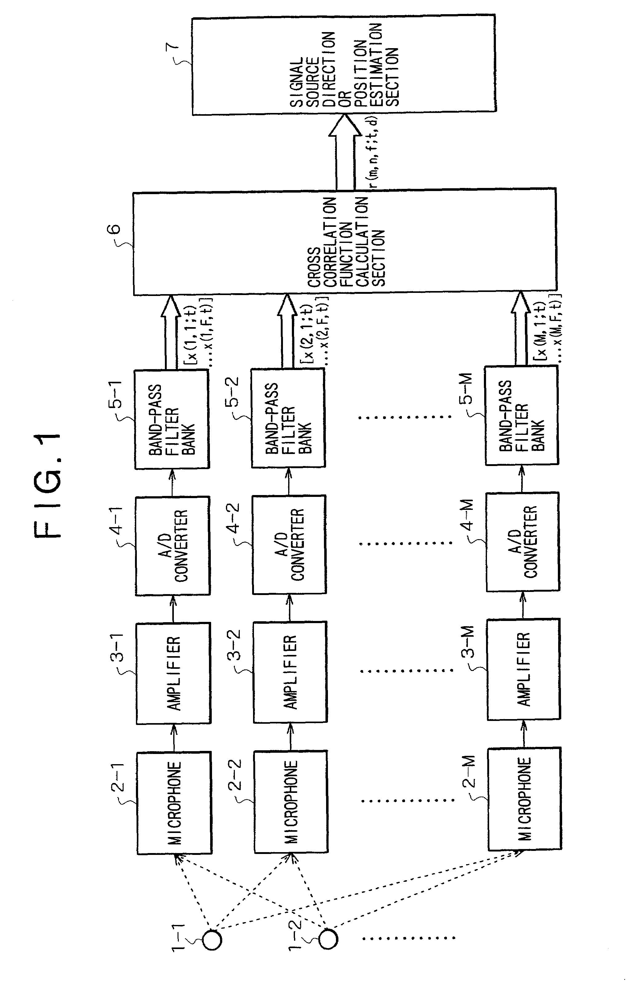
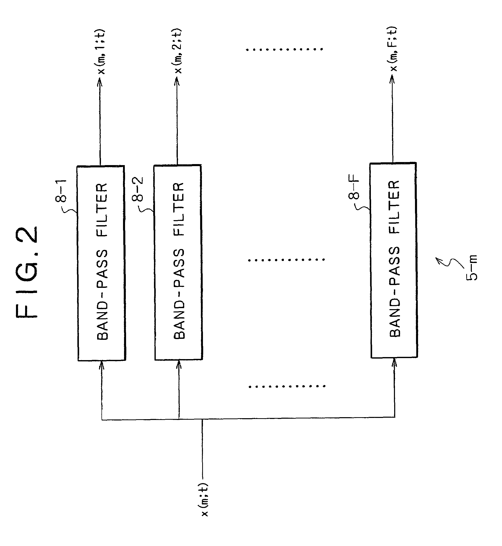
[0081]Referring first to FIG. 1, there is shown a functional configuration of a signal processing apparatus to which the present invention is applied. The signal processing apparatus includes a plurality of (in the embodiment shown, M) reception systems composed of a plurality of (M) microphones 2-1, 2-2, . . . , 2-M for receiving a signal or signals generated from one or more signal sources 1-1, 1-2, . . . , M amplifiers 3-1, 3-2, . . . , 3-M for amplifying the received signals of the microphones 2-1, 2-2, . . . , 2-M, respectively, M A / D converters 4-1, 4-2, . . . , 4-M for converting the amplified signals from the amplifiers 3-1, 3-2, . . . , 3-M into digital signals, respectively, and M band-pass filter banks 5-1, 5-2, . . . , 5-M, respectively, a cross correlation function calculation section 6 for calculating cross correlation functions between frequency band signals for individual combinations of the reception systems for individual frequency bands, and a si...

second embodiment

[Second Embodiment]

[0131]FIG. 9 schematically shows a configuration of another signal processing apparatus to which the present invention is applied.

[0132]Referring to FIG. 9, the signal processing apparatus includes a plurality of (in the embodiment shown, M) reception systems composed of a plurality of (M) microphones 2-1, 2-2, . . . , 2-M for receiving a signal or signals generated from one or more signal sources 1-1, 1-2, . . . , M amplifiers 3-1, 3-2, . . . , 3-M for amplifying the received signals of the microphones 2-1, 2-2, . . . , 2-M, respectively, M A / D converters 4-1, 4-2, . . . , 4-M for converting the amplified signals from the amplifiers 3-1, 3-2, . . . , 3-M into digital signals, respectively, and M band-pass filter banks 5-1, 5-2, . . . , 5-M, respectively, a cross correlation function calculation section 6 for calculating cross correlation functions between frequency band signals for individual combinations of the reception systems for individual corresponding freq...

application example 1

Application of the Signal Source Direction or Position Estimation Apparatus to a TV Conference System, a Supervisory System

[0171]By connecting an output of the signal source direction or position estimation apparatus including a plurality of microphones to a camera control apparatus (refer to FIG. 14), a camera can always be directed to a signal source. Or, where a plurality of cameras are connected to the camera control apparatus, the camera by which the output of the signal source direction or position estimation apparatus should be monitored may be changed over suitably. Or else, in response to position estimation of a signal source, a camera may be zoomed in toward the signal source.


PUM


Abstract

The invention provides a method and apparatus by which the direction in or the position at which a signal source such as a sound source is present is estimated. A signal or signals from a signal source or a plurality of signal sources are received by a plurality of reception apparatus, and the received signals are decomposed into signals of different frequency bands by a plurality of band-pass filters. Then, cross correlation functions between the different frequency band signals are calculated for individual combinations of the reception apparatus for the individual corresponding frequency bands. If the power of noise having no directivity is high in some of the frequency bands, then the cross correlation functions of the frequency band do not exhibit a maximum value. Therefore, an influence of the noise can be suppressed effectively when delay times of the individual reception apparatus which depend upon the direction or directions or the position or positions of the signal source or sources are estimated.

Description

RELATED APPLICATION DATA[0001]The present application claims priority to Japanese Application No. P2000-253306 filed Aug. 24, 2000, which applications are incorporated herein by reference to the extent permitted by law.BACKGROUND OF THE INVENTION[0002]This invention relates to a signal source direction or position estimation method and apparatus for estimating the direction or the position in or at which a signal source such as a sound source is present, and more particularly to a signal source direction or position estimation method and apparatus wherein the direction or the position of a signal source or each of a plurality of signal sources are estimated based on cross correlation functions between signals received by a plurality of reception apparatus.[0003]The present invention further relates to a signal emphasis method and apparatus wherein a signal of a signal source or a plurality of signals of different signal sources are emphasized based on cross correlation functions bet...

Claims


Application Information

Patent Timeline
Patent Type & Authority Patents(United States)
IPC IPC(8): H04R3/00G01S3/802G01S5/20H04N7/15H04R1/40H04R3/04
CPCH04N7/15H04R3/005H04R1/406H04R2499/13
Inventor UKITA, MASAKAZU
Owner SONY CORP
Why Eureka
Try Eureka