Embroidery simulation method and apparatus and program and recording medium

a technology of embroidering simulation and embroidering image, applied in the field of embroidering simulation method, apparatus, program and storage medium, can solve the problem of low quality of simulation imag

Inactive Publication Date: 2006-05-30
SHIMA SEIKI MFG LTD
View PDF8 Cites 7 Cited by
  • Summary
  • Abstract
  • Description
  • Claims
  • Application Information

AI Technical Summary

Benefits of technology

[0006]The invention is an embroidering simulation method including inputting embroidering data for embroidery and outputting an image of completed embroidery, comprising setting a plurality of positions of embroidering points on a two-dimensional plane based on the embroidering data, forming a plurality of stitches between the positions of embroidering points with two-dimensional images of threads, setting a light projecting direction to one direction on the two-dimensional plane, and adding brightness contrast to each of the thread stitch images so that an end portion at one side of the thread stitch image facing the light projecting direction is bright, another end portion at the other side thereof is dark, a change at the central portion of the thread stitch images is bigger than a change at both sides thereof and overall brightness is increased in accordance with an angle formed between a thread direction of the stitch and the light projecting direction within a range where the angle increases from 0 degree to 90 degrees.

Problems solved by technology

However, even when carrying out an embroidering simulation with this method, the obtained stereoscopic image or texture is not always satisfactory, so that the simulation image does not have a quality that can be used as a sample that can be substituted for a real material.

Method used


Image

  • Embroidery simulation method and apparatus and program and recording medium
  • Embroidery simulation method and apparatus and program and recording medium
  • Embroidery simulation method and apparatus and program and recording medium

Examples


Embodiment Construction

[0023]Now referring to the drawings, preferred embodiments of the invention are described below.

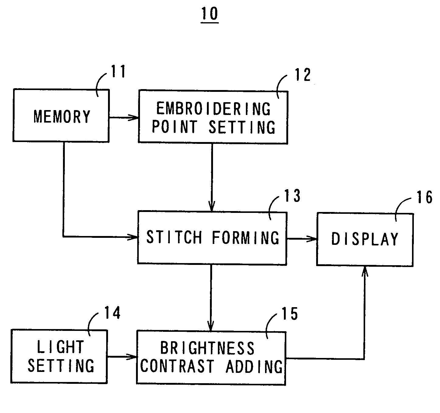
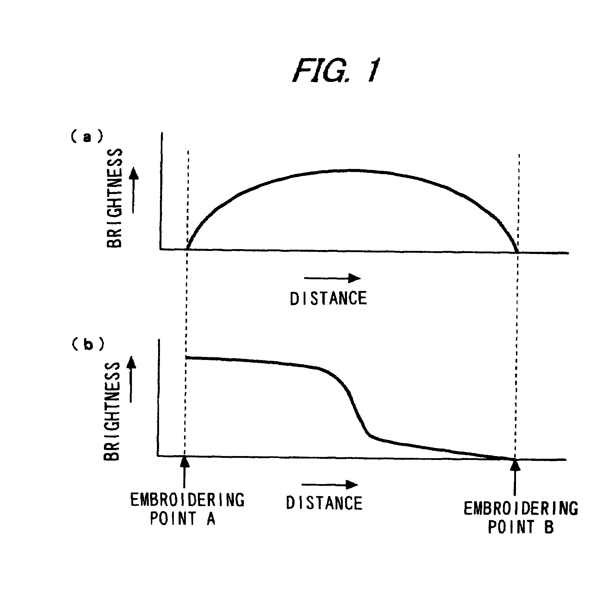
[0024]FIG. 1 shows basic concepts of an embroidering simulation according to the invention, compared with basic concepts disclosed in Japanese Patent No.2596093. FIG. 1(a) shows a brightness change at a stitch between embroidering points disclosed in Japanese Patent No.2596093. FIG. 1(b) shows a brightness change at a stitch between embroidering points according to the invention. In both the concepts, a plurality of positions of embroidering points are set on a two-dimensional plane based on embroidering data, and a stitch is formed between the positions of embroidering points based on the embroidering data.

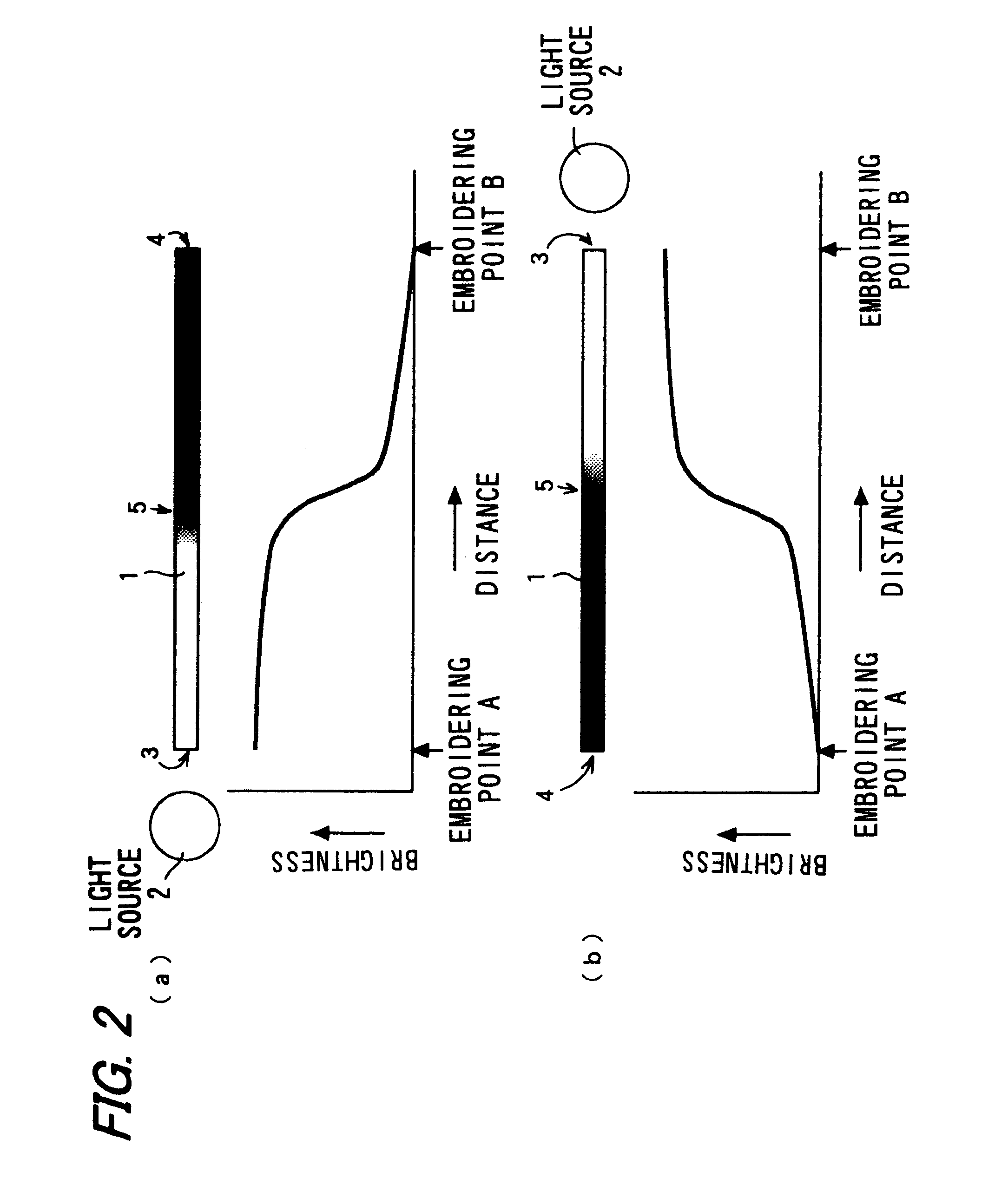
[0025]In Japanese Patent No.2596093, the brightness change is set such that end portions of the region between the embroidering points, that is, embroidering point portions are dark, and that the central portion is bright. In the invention, a light projecting direction is set to one di...


PUM


Abstract

A method for realizing embroidery simulation which can be used as an alternative sample to an actual object. A shade is added to a stitch not to brighten the center of the stitch and to darken the opposite ends thereof as shown at (a) but to brighten a stitch A close to a light source most and to darken a stitch B remote from the light source most as shown at (b). Assuming that the light source is not located on a two-dimensional plane where the stitch exists but a light beam enters obliquely from the upper space, variation of shade is also added in the widthwise direction of a yarn similarly to the longitudinal direction thereof in order to impart three-dimensional feeling thus attaining a simulation image having highly massive feeling.

Description

[0001]This application is the national phase under 35 U.S.C. §371 of PCT International Application No. PCT / JP03 / 03192 which has an International filing date of Mar. 17, 2003, which designated the United States of America and which claims priority on Japanese Patent Application No. JP 2002-108875 filed Apr. 11, 2002, the entire contents of which are hereby incorporated herein by reference.FIELD OF THE INVENTION[0002]The present invention relates to a method, an apparatus, a program and a storage medium for an embroidering simulation with which a completed state of embroidery can be confirmed with images.BACKGROUND OF THE INVENTION[0003]Conventionally, an automated embroidering machine is used for mechanical embroidery. Japanese Patent No.2596093 discloses an embroidering simulation apparatus that displays a stitch image according to embroidering data to form an embroidery pattern, and that changes brightness of the stitch image of a thread that connects embroidering points, between e...

Claims


Application Information

Patent Timeline
Patent Type & Authority Patents(United States)
IPC IPC(8): D05C5/02D05B19/08G06T15/50
CPCG06T15/50D05B19/08G06T2210/16D05B19/02G06T11/20
Inventor TAKEUCHI, NOBUYUKI
Owner SHIMA SEIKI MFG LTD
Why Eureka
Try Eureka