Articulating tool arm with positional feedback

a technology of position feedback and articulating tool arm, which is applied in the direction of manufacturing tools, machine supports, building scaffolds, etc., can solve the problems of failure to successfully address the problem of failure to crack or other failure, and failure to meet the needs of prior ar

a technology of position feedback and articulating tool arm, which is applied in the direction of manufacturing tools, machine supports, building scaffolds, etc., can solve the problems of failure to successfully address the problem of failure to crack or other failure, and failure to meet the needs of prior ar

US7055789B2Inactive Publication Date: 2006-06-06AUTOMATION TOOL COMPANY

Image

  • Articulating tool arm with positional feedback
  • Articulating tool arm with positional feedback
  • Articulating tool arm with positional feedback

Examples


Embodiment Construction

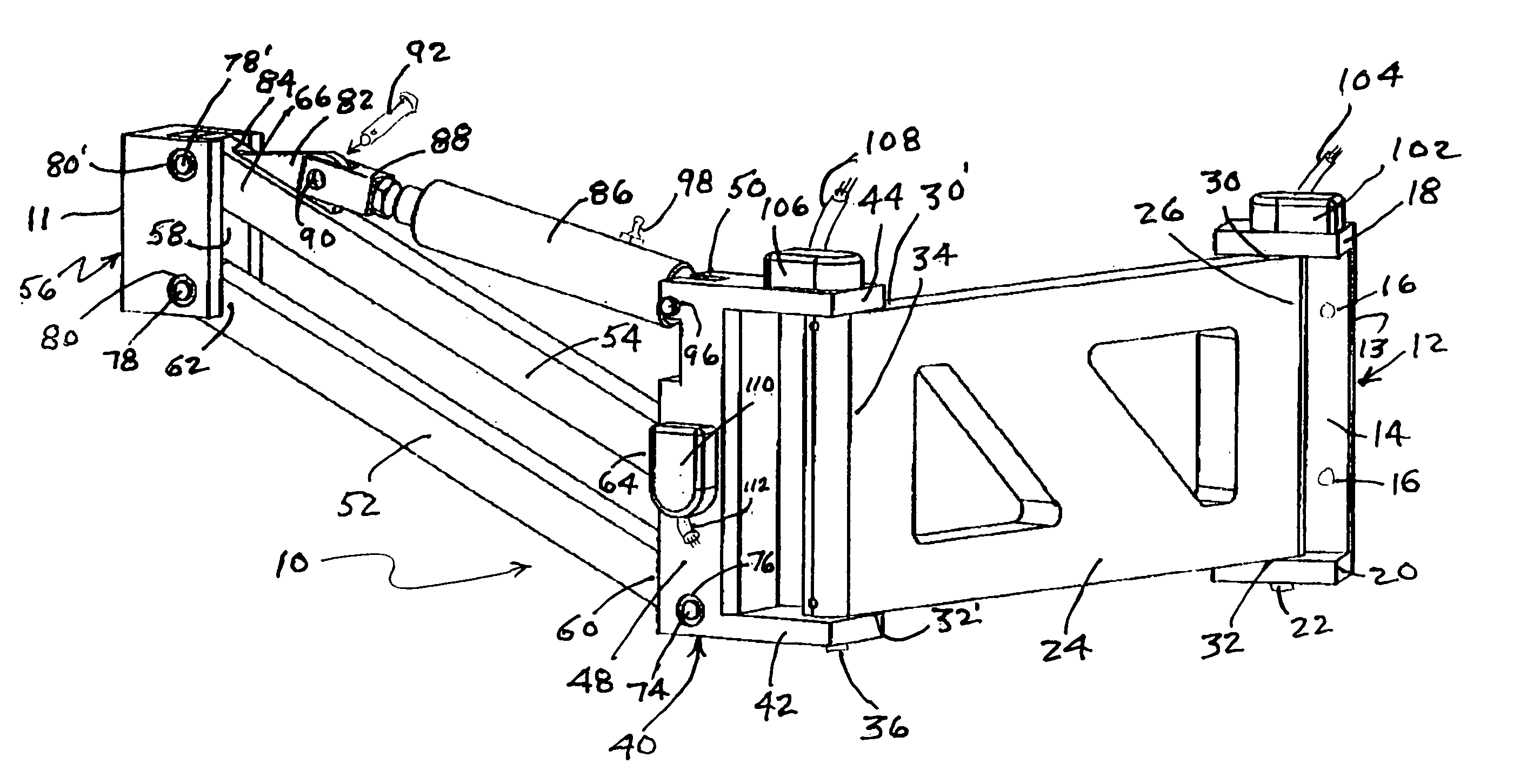
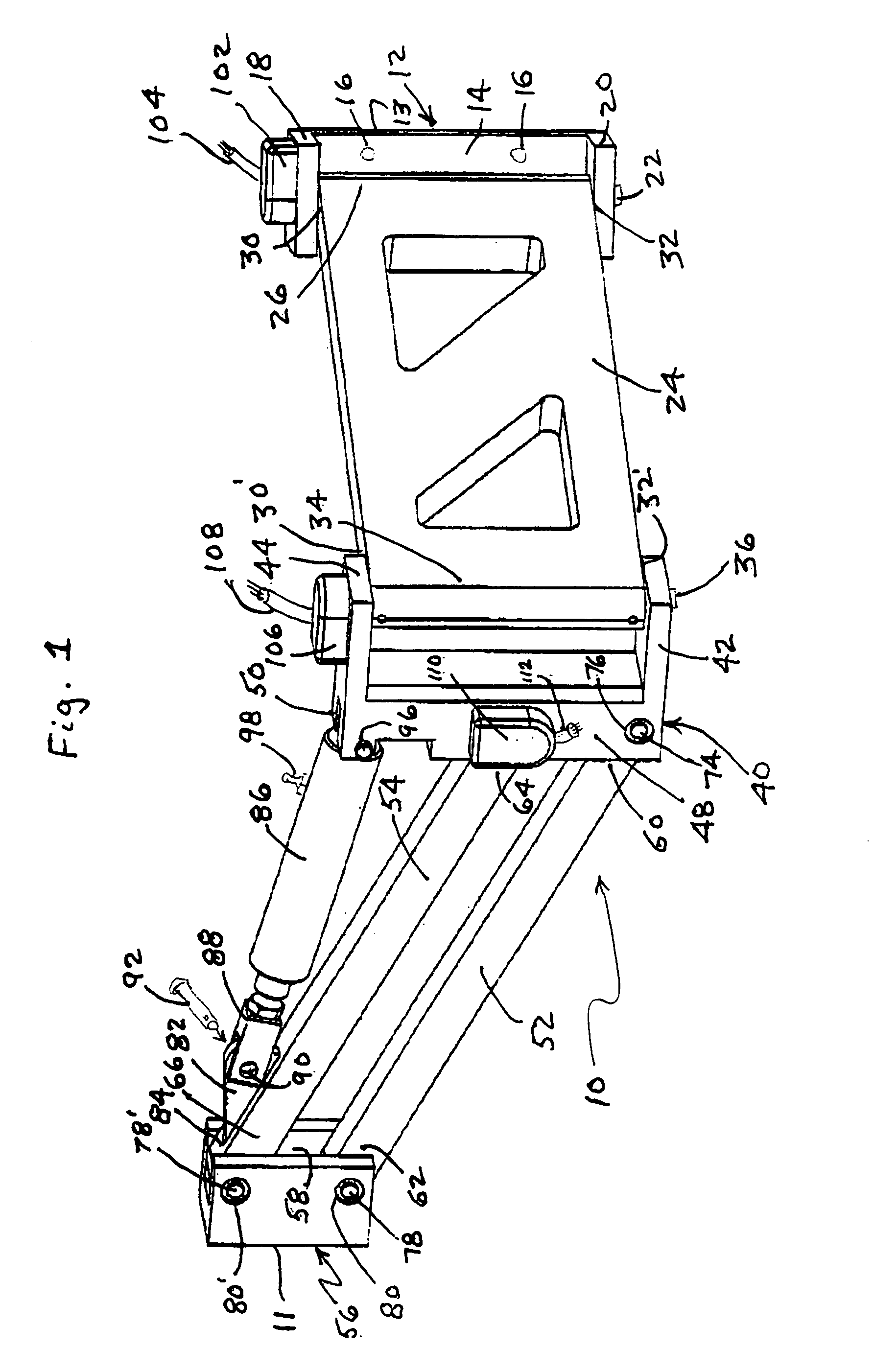
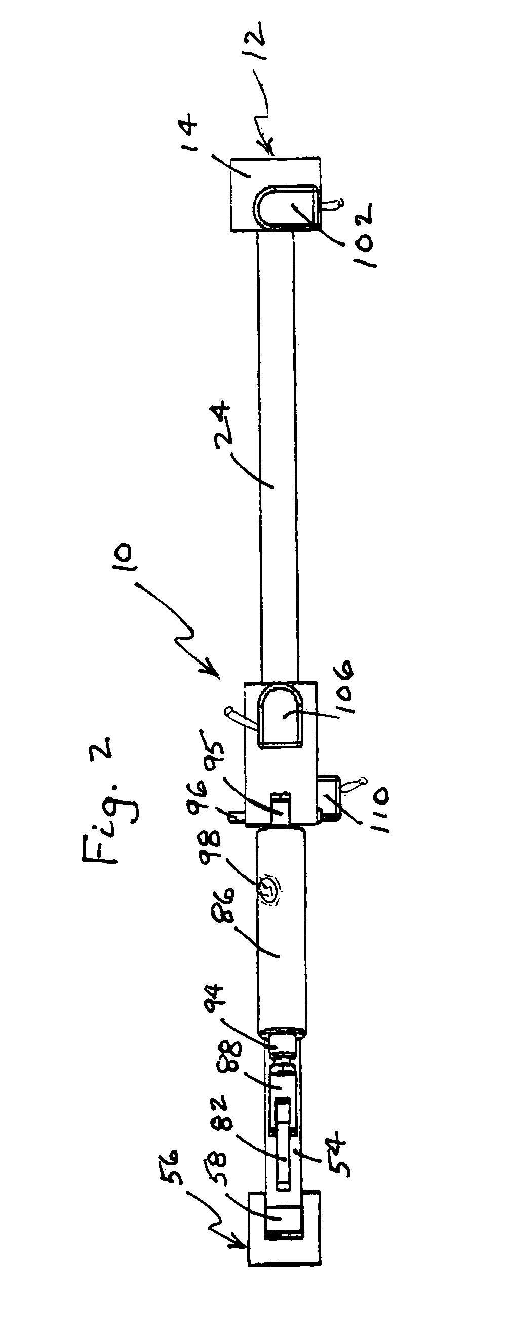
[0031]A apparatus is provided for use in industrial applications where a heavy tool such as an electric screwdriver or pop-riveting gun will be used by a person in an assembly operation. The apparatus combines the function of a standard tool balancing arm used throughout the industry with the ability to monitor its position in three-dimensional space with the use of optical encoders at revolute joints on each axis of movement on the arm. This positional feedback is then transmitted to either: a) the customer's logic controller, or b) to an integral control unit. In either case, the specific parameters required for the application can be set up for monitoring such attributes as point-to-point sequence and location, part tracking, and individual point failure (i.e. screw-driving torque fault). In one embodiment, the apparatus is constructed of high-strength aluminum structural elements anodized for anti-corrosion and aesthetics. Pivot points contain hardened steel bushings and Nylatro...


PUM


Abstract

A power hand-tool support apparatus includes a multi-component articulating arm with pneumatic lifting assist to hold the hand-tool and protect the operator from tool induced torque, the apparatus equipped with positional feedback optical encoders, to communicate with a dedicated control unit to define a selectable datum position of the hand-tool in the work-space with a lock-out of the tool if the positions do not comply with programmed tightening sequences on bolt patterns.

Description

[0001]This application claims the benefit of U.S. Provisional Application No. 60 / 380,503, filed May 14, 2002.FIELD OF THE INVENTION[0002]This invention is directed to an apparatus used at an industrial workstation that includes a hand tool holding device. More particularly the apparatus may include a positional feedback mechanism that provides the tool position and is adapted to be connected to a controlling mechanism and even more particularly may include torque feedback resistance to protect the operator from undue strain and a balancing mechanism to assist lifting the tool.BACKGROUND OF THE INVENTION[0003]Electric and pneumatic powered hand tools are commonly used on assembly lines and assembly stations in industrial manufacturing settings. These tools include drivers for bolts, nuts, screws and like fasteners. While some manufacturing techniques are adaptable to robotic systems, many utilize an operator wielding a powered hand tool. The assembly of a work piece typically involve...

Claims


Application Information

Patent Timeline
06 Jun 2006
Publication
US7055789B2
IPC
E04G3/00; B25B17/00; B25H1/00; F16M11/04
CPC
B25H1/0021; F16M11/04; F16M11/2014; F16M11/24; F16M11/2092; F16M2200/065; F16M2200/044; F16M2200/063
Inventors
LIBBEY, LUCIAN CURT; CRANFORD, JAMES PHILLIP