Block unit for repairing flow passage facilities and method of repairing flow passage facilities

a flow passage and equipment technology, applied in the direction of shaft equipment, shaft lining, mechanical equipment, etc., can solve the problems of large-scale facilities for bypassing service fluid in repair operation

Inactive Publication Date: 2006-06-06
SHONAN GOSEI JUSHI SEISAKUSHO KK +1
View PDF26 Cites 17 Cited by
  • Summary
  • Abstract
  • Description
  • Claims
  • Application Information

AI Technical Summary

Benefits of technology

[0016]According to the present invention, a plurality of block units are joined to each other in the circumferential direction to form the short tubes within a flow passage, and the short tubes are connected to each other in the longitudinal direction to form the continuous tubular assembly having an outer diameter smaller than the inner diameter of the flow passage within the flow passage, so that the pipe, even having a large diameter, can be repaired by introducing the block units into the pipe through a manhole or the like, assembling the block units into the continuous tubular assembly within the flow passage. Moreover, since this operation can be performed while a service fluid is flowing through the flow passage, a desired repair can be made for the flow passage, even having a large diameter, while the service fluid is flowing therethrough.
[0015]To achieve the above object, in accordance with another aspect of the invention there is provided a method of repairing flow passage facilities using block units for repairing flow passage facilities which are assembled into a tubular assembly. The block unit includes at least an inner plate defining an inner surface, and an outer plate disposed along a peripheral edge of the inner plate. The method includes joining the block units adjoining in a circumferential direction preferably with bolts inserted through both circumferential end faces of each the block unit and nuts fitted on the bolts associated therewith to form a short tube within a flow passage, forming a plurality of short tubes in this manner, connecting the short tubes in a longitudinal direction to form a continuous tubular assembly having an outer diameter smaller than an inner diameter of the flow passage, and injecting a grout material into a clearance space formed between the tubular assembly and the flow passage.

Problems solved by technology

However, since a large amount of service fluid must be bypassed, particularly, in the event of repairing a pipe having a large diameter, the repair operation encounters difficulties in installing large scale facilities for bypassing the service fluid.

Method used


Image

  • Block unit for repairing flow passage facilities and method of repairing flow passage facilities
  • Block unit for repairing flow passage facilities and method of repairing flow passage facilities
  • Block unit for repairing flow passage facilities and method of repairing flow passage facilities

Examples


Embodiment Construction

[0046]The present invention will hereinafter be described in connection with several preferred embodiments thereof with reference to the accompanying drawings.

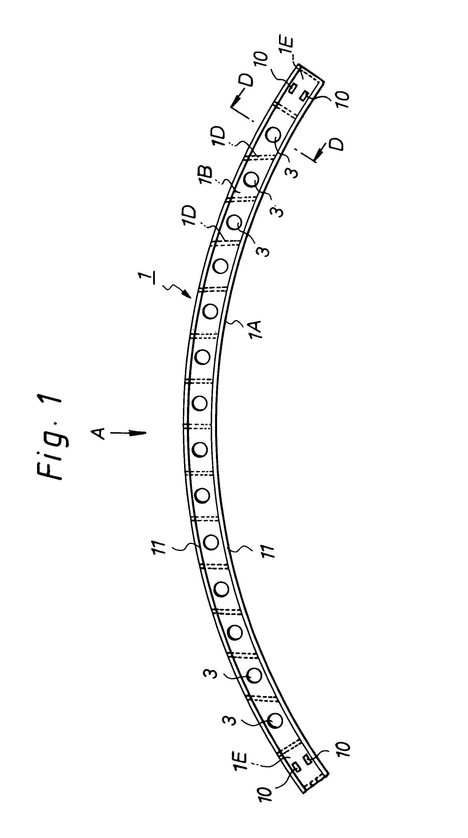
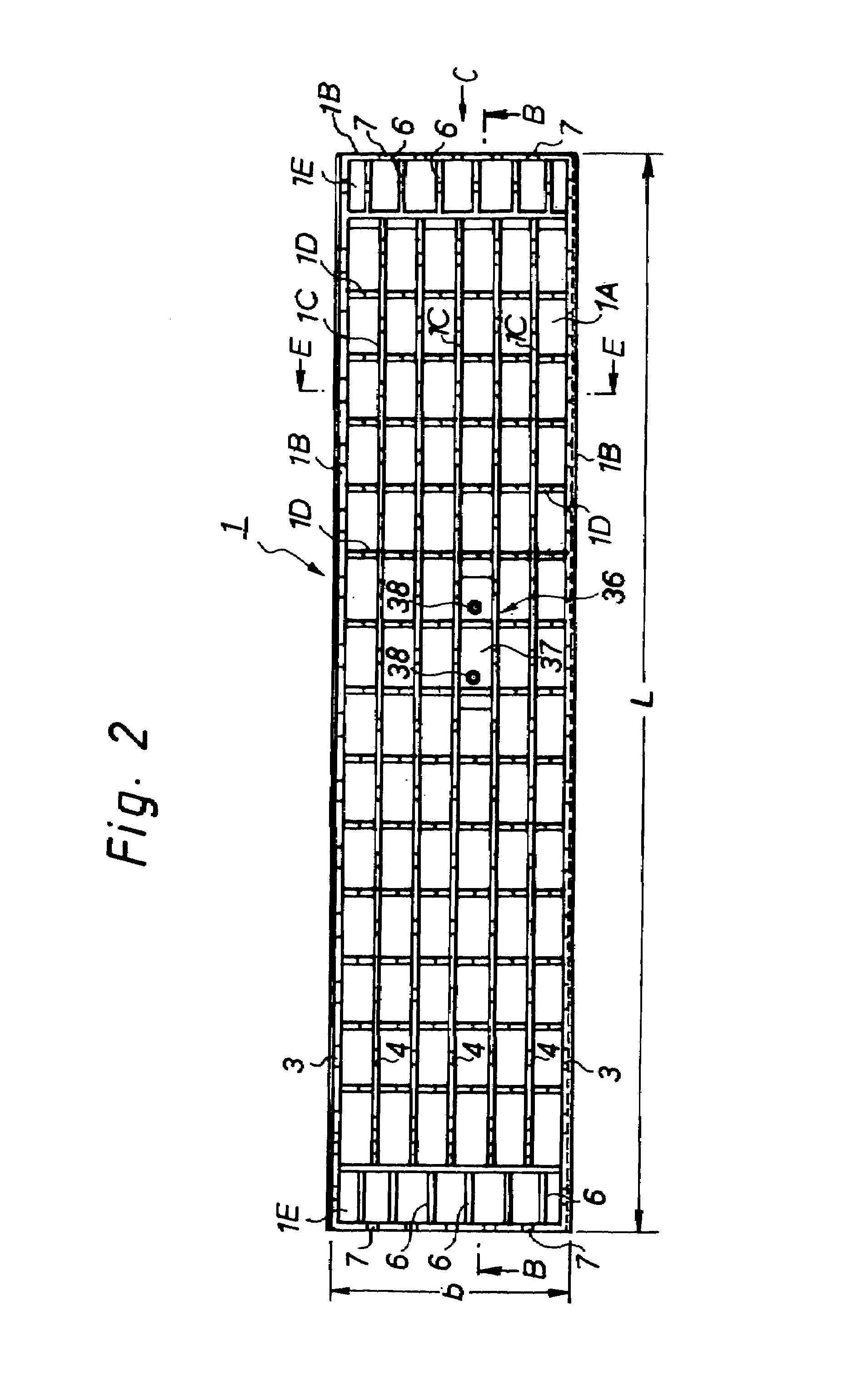
[0047]FIG. 1 is a side view of a block unit for repairing a pipe according to one embodiment of the present invention; FIG. 2 is an outer view (seen in a direction indicated by an arrow A in FIG. 1) of the block unit for repairing a pipe according to the embodiment; FIG. 3 is a cross-sectional view taken along a line B—B in FIG. 2; FIG. 4 is a diagram illustrating the block unit when seen in a direction indicated by an arrow C in FIG. 2; FIG. 5 is a cross-sectional view taken along a line D—D in FIG. 4; FIG. 6 is a cross-sectional view taken along a line E—E in FIG. 2; FIG. 7 is a cross-sectional view, similar to FIG. 6, illustrating an exemplary modification to the embodiment of FIG. 1; FIGS. 8 and 9 are partial cross-sectional views illustrating a structure for attaching a reinforcement material (reinforcing steel); FIG. 10 ...


PUM


Abstract

A block unit for repairing flow passage facilities is provided for permitting a desired repair operation. A method of repairing flow passage facilities using the block unit is also provided. The block unit includes an inner plate defining an inner surface, an outer plate disposed along a peripheral edge of the inner plate, and a plurality of reinforcing ribs for reinforcing the inner plate and the outer plate. The block units adjoining in a circumferential direction are joined together with bolts inserted through both circumferential end faces of each the block unit and nuts fitted on the bolts to form a short tube within a flow passage. The short tubes are connected in a longitudinal direction to form a continuous tubular assembly having an outer diameter smaller than an inner diameter of the flow passage. A grout material is injected into a clearance space formed between the tubular assembly and the flow passage.

Description

PRIORITY INFORMATION[0001]This application is based on and claims priority to Japanese Patent Applications No. 2002-014213, filed on Jan. 23, 2002, and No. 2002-214976, filed on Jul. 24, 2002, the entire contents of which are hereby expressly incorporated by reference herein.BACKGROUND OF THE INVENTION[0002]1. Field of the Invention[0003]The present invention relates to a block unit for repairing flow passage facilities, and to a method of repairing flow passage facilities using the block unit.[0004]2. Description of the Related Art[0005]When an underground pipe, such as pipelines and passageways, becomes defective or too old to perform properly, the pipe is repaired and rehabilitated without digging the earth to expose the pipe and disassembling the sections of the pipe. This non-digging method of repairing an underground pipe has been known and practiced commonly in the field of civil engineering. The pipe lining method utilizes a tubular pipe liner bag that is made of a resin-abs...

Claims


Application Information

Patent Timeline
Patent Type & Authority Patents(United States)
IPC IPC(8): E21D9/00E21D11/00E03F7/00F16L55/162F16L55/163
CPCF16L55/163F16L55/162E03F7/00
Inventor KAMIYAMA, TAKAOYOKOSHIMA, YASUHIRO
Owner SHONAN GOSEI JUSHI SEISAKUSHO KK
Why Eureka
Try Eureka