Automated chest compression apparatus

a chest compression and automatic technology, applied in the field of chest compression apparatus, can solve the problems of affecting the survival rate of patients, the importance of improving resuscitation techniques cannot be overestimated, and the conventional cpr techniques, introduced in 1960, have had limited success both inside and outside the hospital, and achieve the effects of facilitating portability and operation, facilitating portability and space, and easy clearing of doors and windows

Inactive Publication Date: 2006-06-06
ZOLL CIRCULATION
View PDF11 Cites 24 Cited by
  • Summary
  • Abstract
  • Description
  • Claims
  • Application Information

AI Technical Summary

Benefits of technology

[0016]One object of the present invention is to provide a CPR device that is mechanized and will consistently administer CPR in a manner that is more effective than standard manual CPR in terms of vital organ perfusion.
[0017]A further object of the present invention is to provide such a CPR device which is safe for use in a moving ambulance. The device may be configured so that it will administer CPR to a recipient in an automated fashion, thereby freeing the hands of paramedics.
[0018]A further object of the present invention is to provide a CPR device which can be operated with the use of a portable source of energy for at least 15 to 50 minutes. The CPR device will preferably also be capable of use, while transporting a patient on a gurney and in places where a supine position of the patient is impossible.
[0019]Further objects include providing a CPR device which will not slide from its correct position on the patient's chest, will, take up little space so as to easily clear doors and windows, and will otherwise be light and small to facilitate its portability and operation in various environments.
[0020]The present invention, therefore, may be directed to a system for applying CPR to a recipient. The system comprises an automated controller and a compression device. The compression device periodically applies a force to a recipient's thorax under control of the automated controller. The compression device comprises a band, a power mechanism, and a translating mechanism. The band is adapted to be placed around a portion of the torso of the recipient corresponding the recipient's thorax. The power mechanism shortens and lengthens the circumference of the band. By shortening the circumference of the band, radial forces are created acting on at least lateral and anterior portions of the thorax. The translating mechanism translates the radial forces to increase the concentration of the radial forces acting on the anterior portion of the thorax. The power mechanism comprises a tension device for applying a circumferential tensile force to the band.

Problems solved by technology

Conventional CPR techniques, introduced in 1960, have had limited success both inside and outside of the hospital, with only about a 15% survival rate.
Accordingly the importance of improving resuscitation techniques cannot be overestimated.
If, however, more than a few minutes pass between the onset of ventricular fibrillation and the delivery of the first defibrillation shock, the heart may be so deprived of metabolic substrates that defibrillation is unsuccessful.
Myocardial blood flow is much more limited, however, in the range of 5–20% of normal.
However, no patients survived to hospital discharge.
Existing automated systems, such as the pneumatic vest disclosed in the '674 patent (and commercial versions of the same as provided by Cardiologic Systems) present difficulties in situations outside of the hospital.
The inflation console in the Cardiologic system is quite heavy, consumes substantial power, and thus is not practical for mobile environments.

Method used


Image

  • Automated chest compression apparatus
  • Automated chest compression apparatus
  • Automated chest compression apparatus

Examples


first embodiment

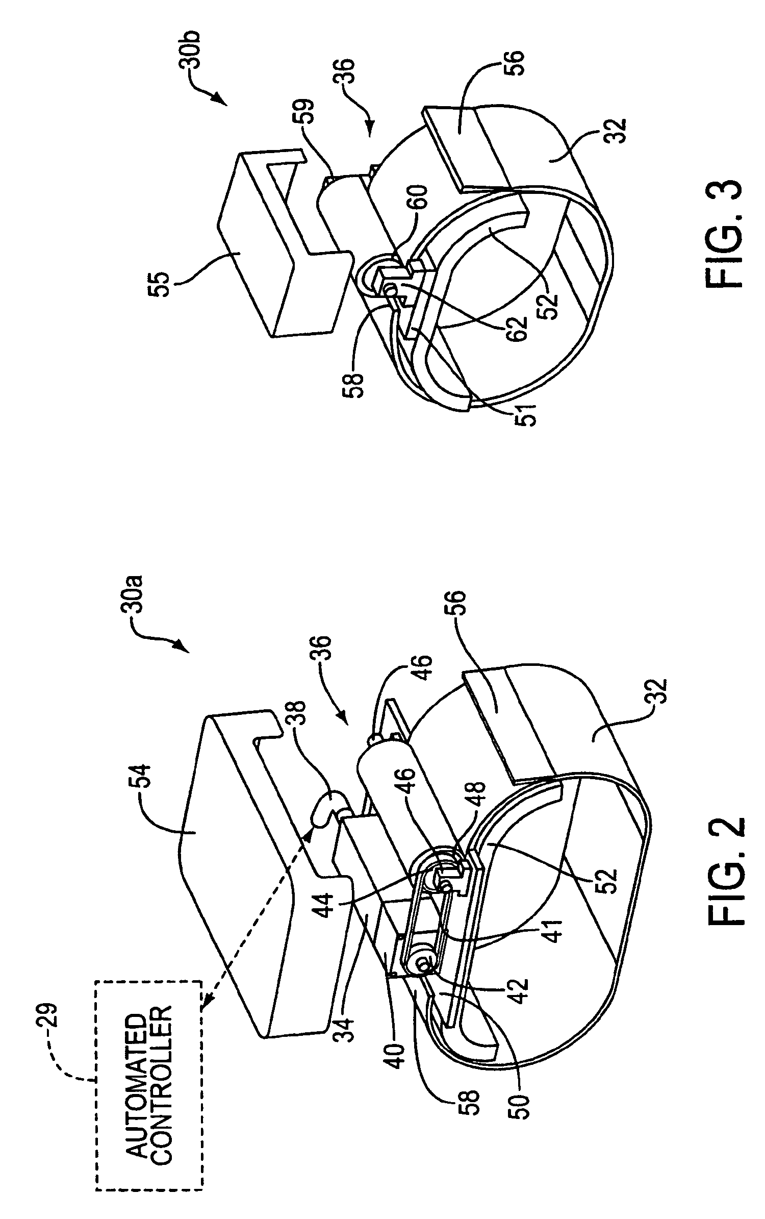
[0035]Referring now to the drawings in greater detail, FIG. 2 shows a CPR device in accordance with the present invention. The illustrated CPR device comprises an automated controller 29 and a compression device 30a for periodically applying a force to a recipient's thorax under control of automatic controller 29. The illustrated compression device 30a comprises a band 32 adapted to be placed around a portion of the torso of the recipient corresponding to the recipient's thorax. A driving sub-system 36 is provided which comprises a driver mechanism for shortening and lengthening the circumference of the band. By shortening the circumference of band 32, radial forces are created acting on at least lateral and anterior portions of the thorax of the recipient.

[0036]In the illustrated embodiment of FIG. 2, the driver mechanism comprises a motorized system. A motor 34 is connected to a gear reducer 40 comprising an output shaft which drives a drive gear 42. Drive gear 42 is coupled to a ...

second embodiment

[0045]In the illustrated second embodiment shown in FIGS. 2 and 4, moldable cushion 52 comprises a water-containing bladder (a hydraulic cushion) placed between band 32 and the anterior portion of the recipient's chest. Motor 34 drives chain 41 through gear reducer 40. Chain 41 then drives cylinder 48 which tightens and. loosens the circumferential band 32. A cover is not shown in FIG. 4 in order to show the details of construction in the illustrated embodiment. A band guard (not shown) may be provided which prevents objects such as clothing from being drawn into the mechanism.

[0046]By shortening and lengthening the circumference of band 32, a chest compression force is applied and released. Moldable cushion 52 helps translate the radial forces created on the thorax of recipient 64 to create an increased concentration of anterior radial forces acting on the anterior portion of the thorax of the recipient 64. The length of each compression cycle may be approximately 400 ms. At the en...


PUM


Abstract

A system applies cardiopulmonary resuscitation (CPR) to a recipient. An automated controller is provided together with a compression device which periodically applies a force to a recipient's thorax under control of the automated controller. A band is adapted to be placed around a portion of the torso of the recipient corresponding to the recipient's thorax. A driver mechanism shortens and lengthens the circumference of the band. By shortening the circumference of the band, radial forces are created acting on at least lateral and anterior portions of the thorax. A translating mechanism may be provided for translating the radial forces to increase the concentration of anterior radial forces acting on the anterior portion of the thorax. The driver mechanism may comprise a tension device for applying a circumference tensile force to the band. The driver mechanism may comprise an electric motor, a pneumatic linear actuator, or a contracting mechanism defining certain portions of the circumference of the band. The contracting mechanism may comprise plural fluid-receiving cells linked together along the circumference of the band. The width of each of the fluid-receiving cells becomes smaller as each cell is filled with a fluid. This causes the contraction of the band and a resulting shortening of the circumference of the band.

Description

[0001]This application is a continuation of U.S. application Ser. No. 09 / 188,065 filed Nov. 9, 1998, now abandoned.BACKGROUND OF THE INVENTION[0002]1. Field of the Invention[0003]The present invention relates to an automated chest compression apparatus for the automated administration of CPR.[0004]2. Description of the Related Art[0005]Each year there are more than 300,000 victims of cardiac arrest. Conventional CPR techniques, introduced in 1960, have had limited success both inside and outside of the hospital, with only about a 15% survival rate. Accordingly the importance of improving resuscitation techniques cannot be overestimated. In the majority of cardiac arrests, the arrest is due to ventricular fibrillation, which causes the heart to immediately stop pumping blood. To treat ventricular fibrillation, defibrillation is administered which involves the delivery of a high energy electric shock to the thorax to depolarize the myocardium, and to allow a perfusing rhythm to restar...

Claims


Application Information

Patent Timeline
Patent Type & Authority Patents(United States)
IPC IPC(8): A61H31/00A61H23/04
CPCA61H9/0078A61H31/006A61H2201/5007A61H2031/003A61H2011/005A61H2201/1238Y10S601/06
Inventor HALPERIN, HENRY R.
Owner ZOLL CIRCULATION
Why Eureka
Try Eureka