Push-on switch

a push-on switch and switch technology, applied in the direction of snap-action arrangements, contact surfaces, contact shape/structure, etc., can solve the problems of heat adversely affecting the switch base, and achieve the effect of reducing the possibility of switch base deformation and stable performan

Inactive Publication Date: 2006-06-06
PANASONIC CORP
View PDF9 Cites 18 Cited by
  • Summary
  • Abstract
  • Description
  • Claims
  • Application Information

AI Technical Summary

Benefits of technology

[0024]With this structure, the push-on switch of the present invention can reduce a possibility of deformation of the switch base due to heat applied to it when being soldered, for instance, thereby providing the push-on switch with a stable performance.

Problems solved by technology

For this reason, switch base 301 is subject to an adverse influence of heat when being connected with solder to a wiring board of an end use product.

Method used


Image

  • Push-on switch
  • Push-on switch
  • Push-on switch

Examples


first embodiment

[0036]Referring now to FIG. 1 and FIG. 2, description is provided more concretely of a structure of the first embodiment according to the present invention.

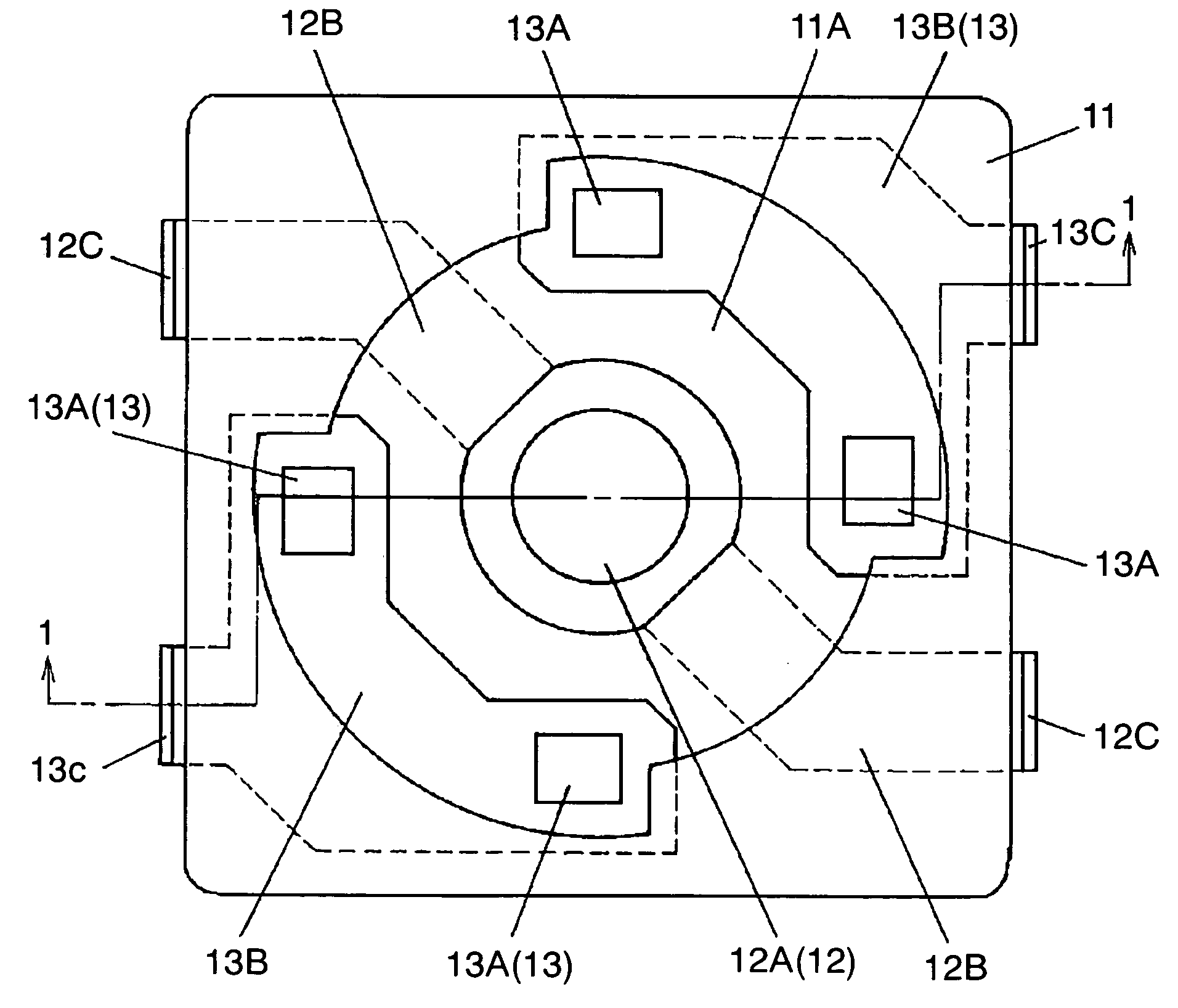
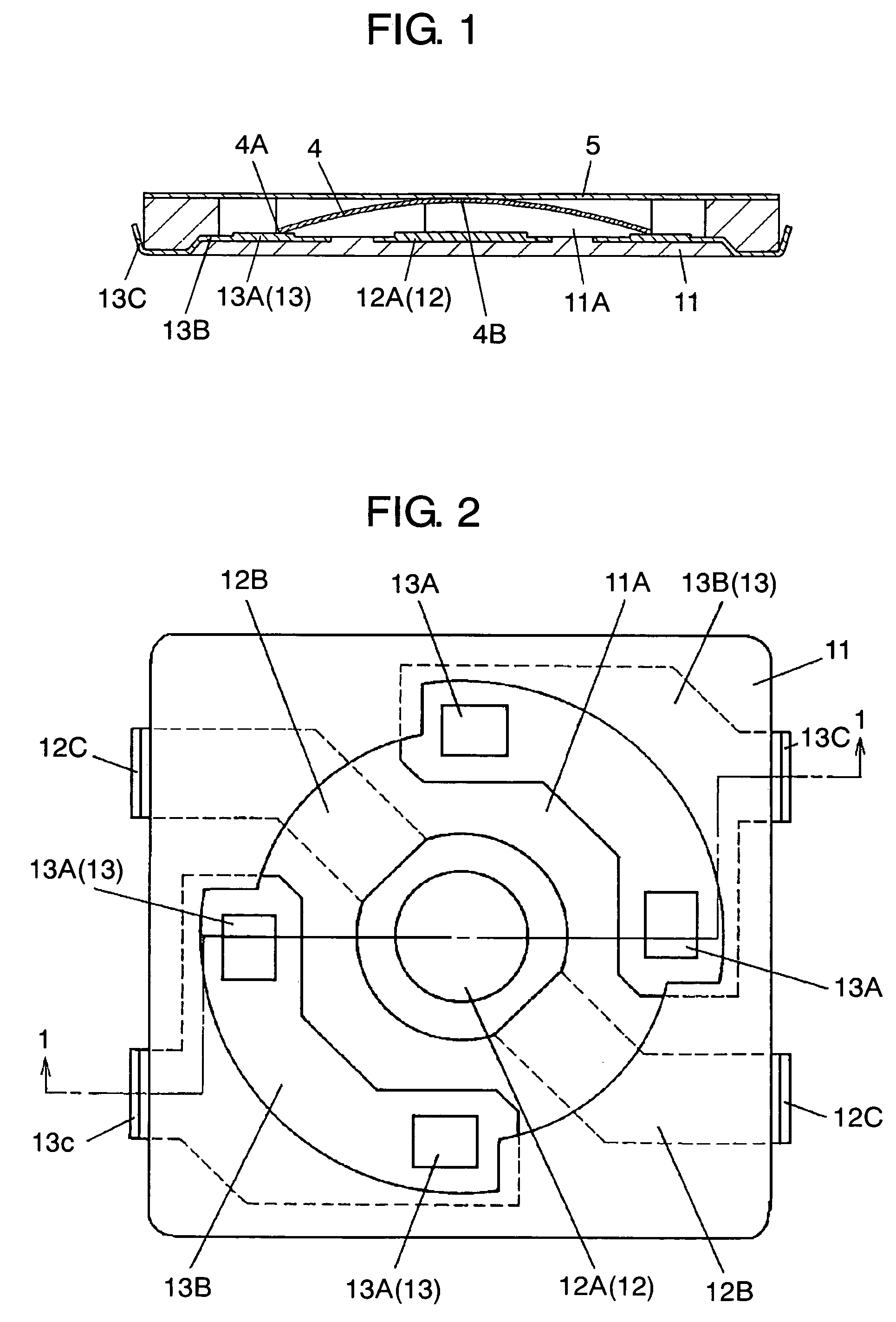
[0037]FIG. 1 is a cross sectional view of a push-on switch according to the first embodiment of this invention, and FIG. 2 is a plan view of a switch base of the push-on switch shown in FIG. 1. The cross sectional view of FIG. 1 depicts the structure in which a complete assembly is sectioned along the line 1—1 shown in FIG. 2.

[0038]In switch base 11 made of an insulation resin shown in FIG. 1, center stationary contact 12 representing a first stationary contact is secured to a bottom surface in the center of open-top recess 11A, and outer stationary contacts 13 representing second stationary contacts are secured to the bottom surface at positions along an outer brim of recess 11A and confronting each other across center stationary contact 12, all by means of insertion molding.

[0039]Center contact point 12A of center stationary co...

second embodiment

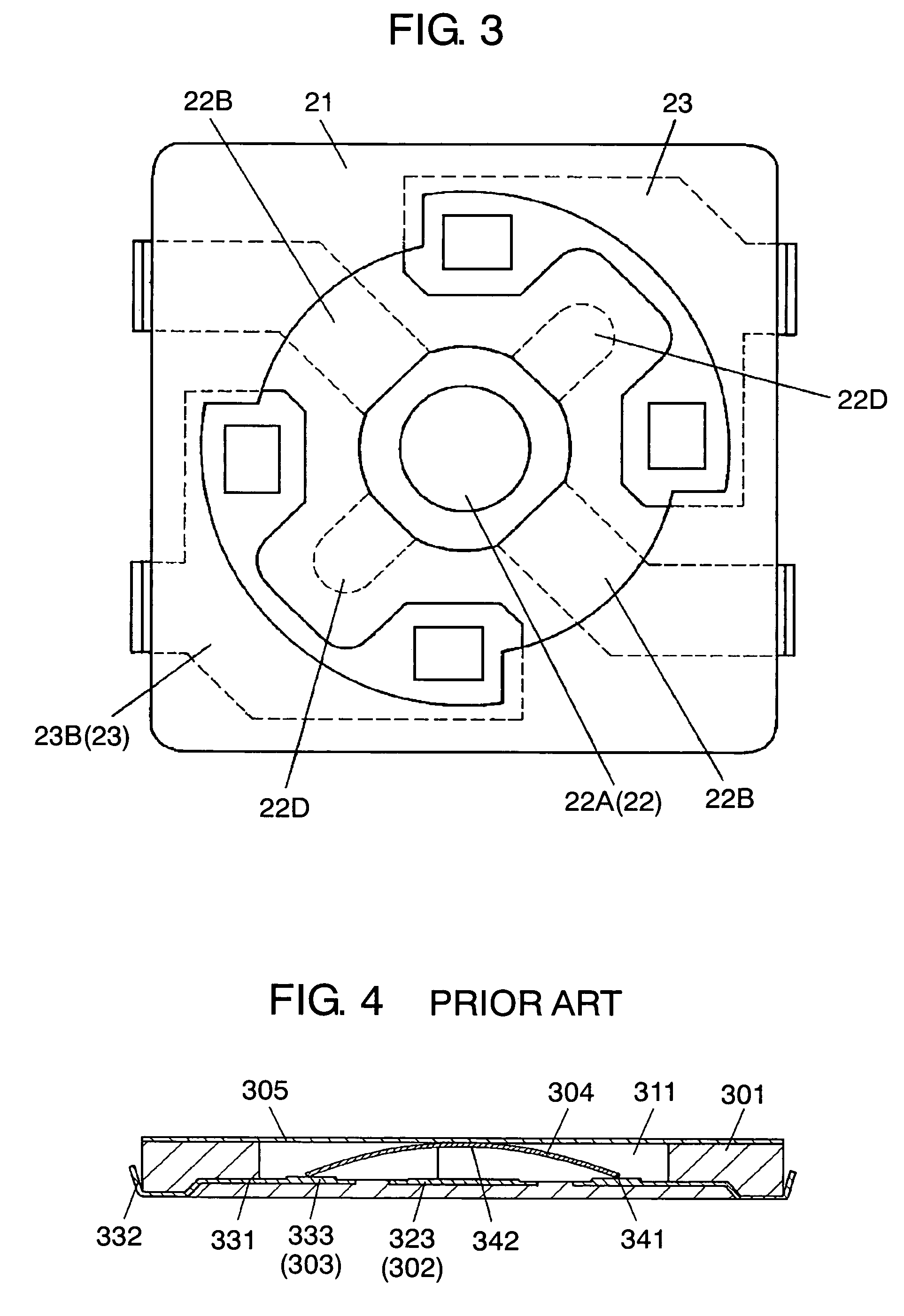
[0048]FIG. 3 is a plan view of a switch base according to the second exemplary embodiment of the present invention. Description will be provided of a push-on switch of this embodiment shown in FIG. 3 with the priority given to different parts from those of the first exemplary embodiment shown in FIG. 1 and FIG. 2.

[0049]That is, switch base 21 illustrated in FIG. 3 is provided, in addition to what are shown in the first exemplary embodiment of FIG. 2, with second lead paths 22D secured into embedment to a recess in switch base 21 in a manner to extend in directions along a diagonal line toward respective areas where outer stationary contacts 23 defining the second stationary contacts are secured from center contact point 22A of center stationary contact 22 defining the first stationary contact secured by means of insertion molding.

[0050]While the individual second lead paths 22D extend toward corner areas of L-shaped outer lead paths 23B, they are arranged with a predetermined distan...


PUM


Abstract

A first stationary contact (i.e., center stationary contact) has a center contact point exposed at the center on the bottom of a recess in a square-shaped switch base as viewed from the above. The first stationary contact is disposed to the bottom of the recess with its lead paths extended along one of diagonal lines of the square-shaped switch base from the center contact point toward both side edges of the switch base. Second stationary contacts (i.e., outer stationary contacts) are arranged at positions along an outer brim of the recess in a line-symmetrical manner about the one of the diagonal lines in areas opposite each other along the other diagonal line. The first stationary contact and the second stationary contacts are arranged in this manner and secured into embedment by means of insertion molding in the bottom of the recess in the switch base of an insulation resin.

Description

FIELD OF THE INVENTION[0001]The present invention relates to push-on switches to be mounted and used in control units of electronic devices such as digital still cameras (DSC), portable phones, and the like.BACKGROUND OF THE INVENTION[0002]With the advancement of electronic devices toward downsizing and low-profiling in recent years, there is a strong demand for reduction in size and thickness of push-on switches for use in the electronic devices while also providing superior electrical and mechanical characteristics. Description is provided of one such push-on switch of the prior art with reference to FIG. 4 and FIG. 5.[0003]FIG. 4 is a cross sectional view of a conventional push-on switch, and FIG. 5 is a plan view of a switch base of the push-on switch shown in FIG. 4. Here, FIG. 4 illustrates a structure in which a complete assembly of the push-on switch is sectioned along the line 4—4 shown in FIG. 5.[0004]In FIG. 4 and FIG. 5, switch base 301 made of an insulation resin is gen...

Claims


Application Information

Patent Timeline
Patent Type & Authority Patents(United States)
IPC IPC(8): H01H5/18
CPCH01H1/5805H01H13/48H01H2001/5888
Inventor OYAGI, SHINGOYANAI, YASUNORIYAGI, YOSHIKAZUWATANABE, HISASHI
Owner PANASONIC CORP
Why Eureka
Try Eureka