Bus bar and method of manufacturing the bus bar

a bus bar and manufacturing method technology, applied in the field of bus bars, can solve the problems of reducing yield, difficult to apply bending work to material having a high hardness, and body having a predetermined flexibility may be deformed, so as to achieve more flexibility, secure workability, and high hardness

Inactive Publication Date: 2013-11-07
TOGO SEISAKUSYO CORP
View PDF7 Cites 8 Cited by
  • Summary
  • Abstract
  • Description
  • Claims
  • Application Information

AI Technical Summary

Benefits of technology

[0011]In the invention claimed in claim 7, at least either the compensating member or the body has a side which is opposed to the other and has a misalignment preventing portion which prevents misalignment between the compensating member and the body. Consequently, the terminal can be formed so as to have a desired thickness while relative misalignment is prevented between the compensating member and the body, in the same manner as in the above-described invention claimed in claim 4 or 5.
[0012]In the invention claimed in any one of claims 8 to 14, the body is formed in a three-dimensional manner so as to have a plurality of bent portions with different bending directions. In this case, more flexibility is required of the body since the plural bent portions having different bending directions are formed. Even in this case, the terminal is formed of the same material as that of the body in the seamless manner integrally with the body and is further formed so as to have a higher hardness than the bent portion. Accordingly, the bus bar can balance securement of workability and improvement in the yield.
[0013]In the invention claimed in claim 15, at least one bent portion is formed on the body and pressure is applied to at least one end of the body thereby to form a plate-shaped or bar-like terminal on the body and simultaneously, to render a hardness of the terminal higher than a hardness of the body. As a result, the terminal is formed of the same material as that of the body in the seamless manner integrally with the body and is further formed into a plate shape or a bar shape so as to have a higher hardness than the bent portion. Thus, the number of working steps is reduced by simultaneously executing the forming of the terminal and the work hardening. Consequently, the bus bar can be manufactured which balances securement of workability and improvement in the yield as described above in relation to the invention claimed in claim 1.

Problems solved by technology

However, the terminal formed of the material different from that of the body necessitates a work of welding, pressure bonding or the like to the body, thereby reducing the yield.
In this case, however, there is a possibility that the body having a predetermined flexibility may be deformed during the mounting to the terminal block.
However, it would be difficult to apply a bending work to the material having a high hardness.
According, ordinary bus bars have a problem of difficulty in balancing securement of workability and improvement in the yield.

Method used


Image

  • Bus bar and method of manufacturing the bus bar
  • Bus bar and method of manufacturing the bus bar
  • Bus bar and method of manufacturing the bus bar

Examples


first embodiment

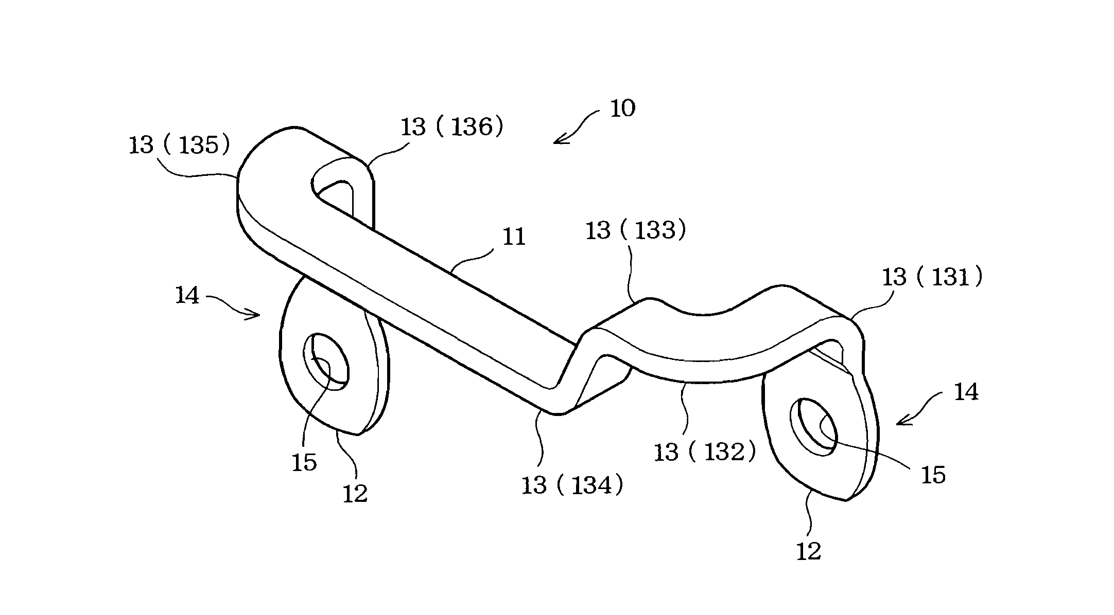
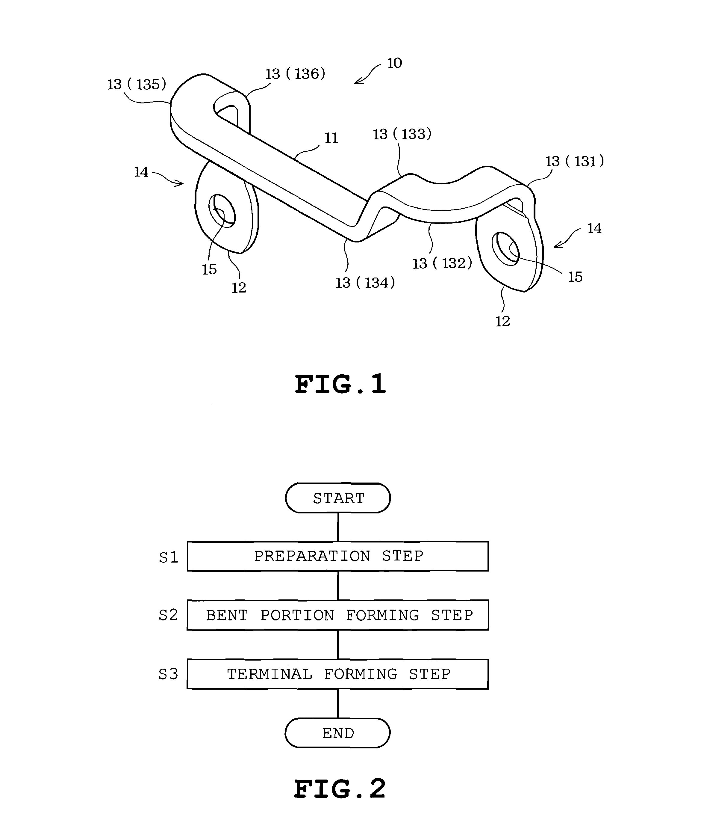
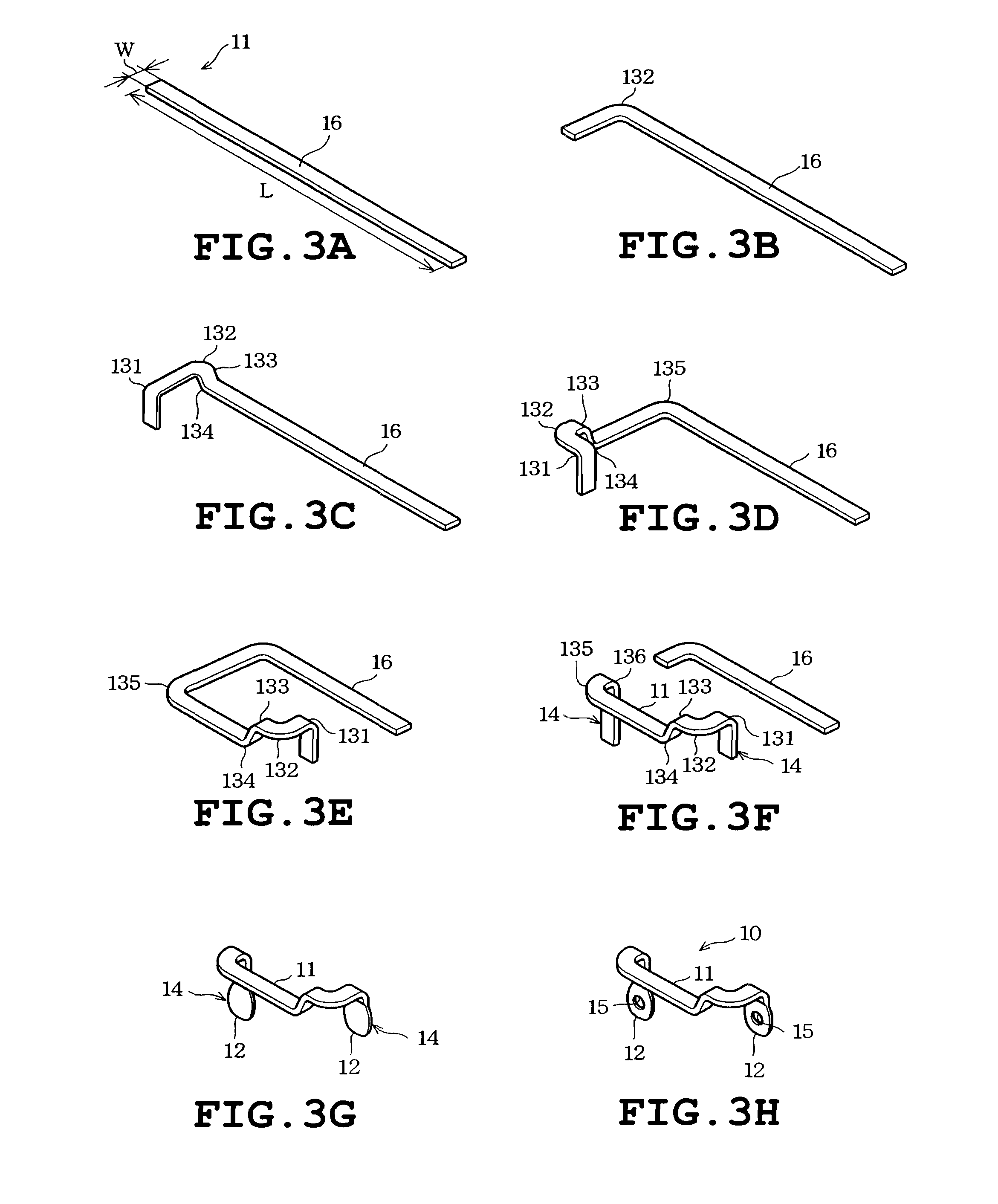
[0026]The bus bar and the bus bar manufacturing method will be described with reference to FIGS. 1 to 5. The bus bar 10 includes a body 11 and two terminals 12 as shown in FIG. 1. The body 11 is formed into the shape of a flat plate having a rectangular section. The body 11 should not be limited to the rectangular section but may be formed into different shapes including a bar shape with a circular section, or with an elliptic or H-shaped section. The body 11 has a plurality of bent portions 13. The bent portions 13 of the body 11 include bent portions 131, 133, 134 and 136 each formed by a flatwise bending method in which each bent portion is bent in a direction of plate thickness of the flat plate-shaped body 11. Bent portions 132 and 135 are formed by an edgewise bending method in which each bent portion is bent in a direction of plate width of the body 11. When the description is common to all the bent portions 131 to 136, the “bent portions 13” will be used in the following de...

second embodiment

[0044]The bus bar has a folded portion 20 formed at the end 14 of the body 11 as shown in FIG. 6A. The folded portion 20 is folded upward relative to the body 11 to be stacked on the body 11 as viewed in FIG. 6A. The folded portion 20 has a convex portion 21 formed on a side thereof opposed to the body 11. The convex portion 21 is located so as to correspond to a concave portion 22 provided in the body 11 when the folded portion 20 has been stacked on the body 11. More specifically, the convex portion 21 engages the concave portion 22 when the folded portion 20 has been stacked on the body 11, as shown in FIG. 6B. The convex and concave portions 21 and 22 prevent misalignment between the folded portion 20 and the body 11 during the pressing. Thus, the convex and concave portions 21 and 22 serve as a misalignment preventing portion defined in the claims.

[0045]In the above-described state, pressure is applied to the end 14 of the bus bar including the folded portion 20 and the body 1...

third embodiment

[0051]In the bus bar the end 14 of the body 11 is annularly folded before the terminal forming step as shown in FIG. 8A. The end 14 is folded about three-quarters of the circumference to be stacked on the body 11. More specifically, the end 14 of the body 11 is formed into a generally annular shape. When pressure is applied to the end 14 in the stacked state, the terminal 31 with the hole 30 is formed as shown in FIG. 8B. The hole 30 is available as the through screw hole. The terminal 31 with the hole 30 is thus formed by folding the end 14 of the body 11 substantially into the annular shape, stacking the folded end 14 on the body 14 and pressing the stacked end 14. For example, when the screw hole is formed by cutting with the use of a drill or by pressing with the use of a punch, the cutting work or the pressing work results in material loss in a cut portion. In the embodiment, however, the end 14 is folded into the generally annular shape so that the hole 30 is formed, whereby ...


PUM

PropertyMeasurementUnit
hardnessaaaaaaaaaa
thicknessaaaaaaaaaa
bendingaaaaaaaaaa

Abstract

A bus bar includes a body having at least one bent portion and a plate-shaped or bar-like terminal located on at least one end of the body and formed of a material identical with a material of the body integrally with the body in a seamless manner. The terminal has a higher hardness than the bent portion.

Description

TECHNICAL FIELD[0001]The present invention relates to a bus bar and a method of manufacturing the bus bar.BACKGROUND ART[0002]For example, bus bars are known which electrically connect between terminal blocks of an inverter device, a battery or the like (see Patent Document 1, for example). One of the bus bars includes a body having a bent portion to which a bending work is applied and terminals provided on ends of the body respectively. Accordingly, the body of the bus bar is formed of a relatively soft material having such flexibility as to be formed into the bent portion. On the other hand, each terminal of the bus bar is threadably mounted to the terminal block, for example. In this case, each terminal necessitates a certain degree of hardness. Accordingly, a terminal member formed of a material different from that of the body is mounted to the body by welding, pressure bonding or the like.[0003]However, the terminal formed of the material different from that of the body necessi...

Claims


Application Information

Patent Timeline
Patent Type & Authority Applications(United States)
IPC IPC(8): H01B5/02
CPCH01B5/02H01R43/16H02B1/20H01R25/14B21C37/04B21C37/045B21F1/00B21F5/00B21K25/00
Inventor OKADA, HIROKISATO, MASAYUKIKAMIYA, TOSHIMITSU
Owner TOGO SEISAKUSYO CORP
Why Eureka
Try Eureka