Pressure fault device

a fault device and fault technology, applied in the direction of fluid pressure measurement using inductance variation, service pipe system, instruments, etc., can solve the problems of system may need to be changed, and high or low pressure or differential pressur

Inactive Publication Date: 2006-06-13
MIDWEST INSTR
View PDF7 Cites 9 Cited by
  • Summary
  • Abstract
  • Description
  • Claims
  • Application Information

AI Technical Summary

Benefits of technology

[0008]Accordingly, it is an object of the present invention to provide an improved simple device for determining in advance or during troubleshooting procedures where a flow, pressure or differential pressure problem has occurred.
[0009]It is another object of the present invention to provide an improved device that saves time in determining where a flow problem has occurred.

Problems solved by technology

At times, such systems experience too high or too low pressures or differential pressures which may be caused by a number of events.
For example, the system may be partially obstructed by particle buildup within a flow line thereof, a mechanism malfunction may have partially shut a valve causing high pressure buildup, a filter may need changing, etc.
In many systems, a problem regarding excessively high or low pressure or differential pressures may not be discovered for a substantial amount of time after it has occurred.
Thus, pressure or flow problems more than likely may only be discovered during those times. In many situations where such flow problems occur, the problem requires minor repair or maintenance, such as simply changing a filter.
However, in many systems, troubleshooting takes a substantial amount of time.
For example, troubleshooting procedures may take from several hours to several days to determine the cause of a pressure or flow problem, whether minor or major.

Method used


Image

  • Pressure fault device
  • Pressure fault device
  • Pressure fault device

Examples


first embodiment

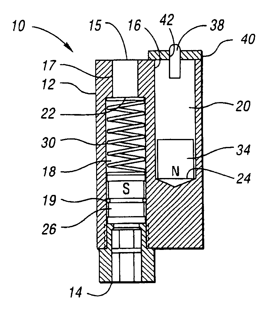
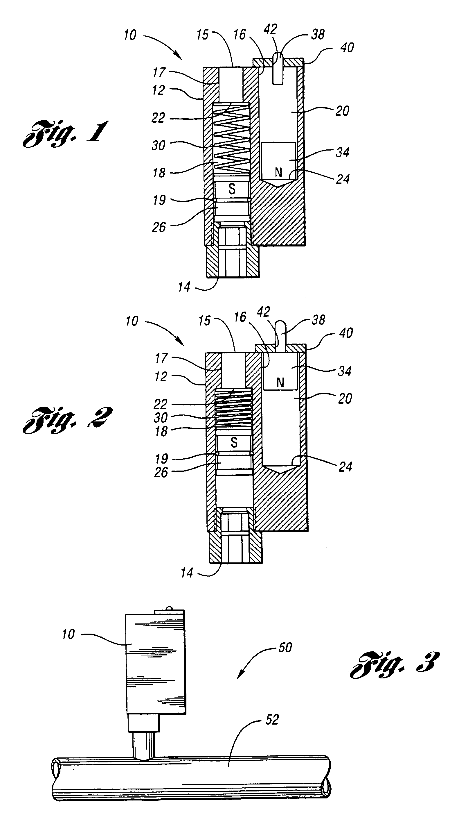
[0024]FIG. 1 illustrates a pressure fault device 10 at atmospheric pressure for indicating an inlet threshold pressure. As shown, device 10 includes a housing 12 which generally includes an inlet aperture 14, an atmospheric aperture 15, and an indicator aperture 16. Apertures 14 and 15 are in fluid communication with first bore 18. First bore 18 extends from inlet aperture 14 to shoulder 22 having inner walls 17 extending to atmospheric aperture 15. Second bore 20 extends from indicator aperture 16 to second end 24. In this embodiment, second bore is preferably formed adjacent and substantially parallel to first bore 18. Also, first bore 18 preferably has cylindrical walls defining a diameter of first bore 18. Likewise, second bore 20 preferably has cylindrical walls defining a diameter of the second bore. It is to be noted that the housing is made of material that is not capable of being magnetized, such as plastic, aluminum, non-magnetic stainless steel, ceramic, brass or any othe...

second embodiment

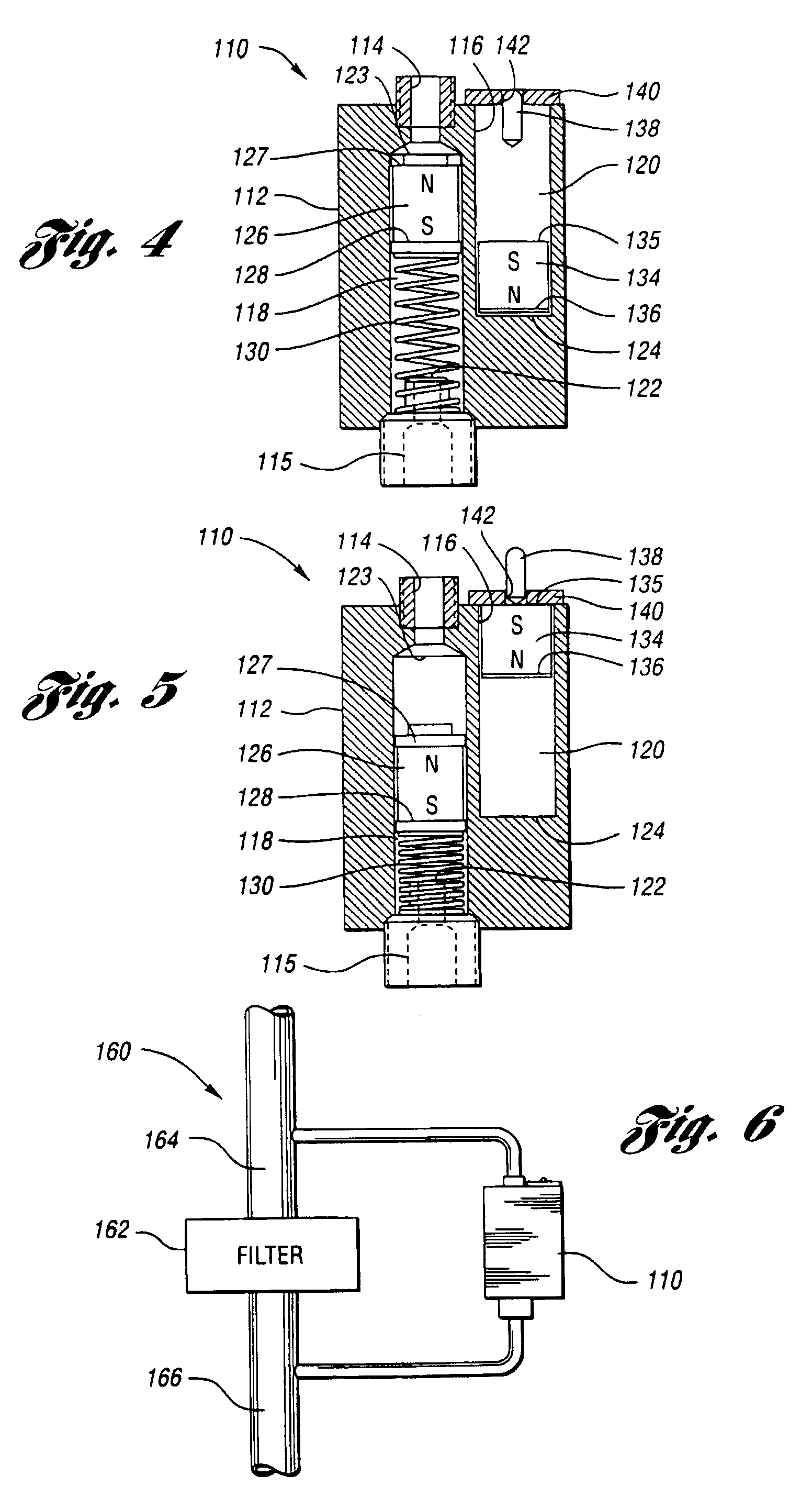
[0033]FIG. 4 illustrates a pressure fault device 110 for indicating a threshold differential pressure. As shown, device 110 includes a housing 112 which generally includes high pressure port 114, low pressure port 115, and indicator aperture 116. High pressure port 114 and low pressure port 115 are in fluid communication with first bore 118. Indicator aperture 116 is in fluid communication with second bore 120. First bore 118 extends from high pressure port 114 at high portion 123 to low pressure port 115 at low portion 122. Second bore 120 extends from indicator aperture 116 to second bore end 124. First bore 118 preferably has cylindrical walls defining a diameter of first bore 118. Likewise, second bore 120 preferably has cylindrical walls defining a diameter of second bore 120.

[0034]Device 110 includes components similar as to components of device 10 above. Particularly, magnetic piston 126, magnetic responder 134, indicator 138, and latching plate 140, are respectively similar ...


PUM

PropertyMeasurementUnit
pressureaaaaaaaaaa
pressureaaaaaaaaaa
threshold pressureaaaaaaaaaa

Abstract

The invention involves a pressure fault device for indicating a threshold pressure or a threshold differential pressure. The present invention provides a cost effective way to determine where a pressure problem has occurred. The device includes a housing having at least one inlet aperture and an indicator aperture and having first and second bores in fluid communication respectively with one inlet aperture and the indicator aperture. The device further includes a magnetic piston which is biased in the first bore toward one inlet aperture and moveable a predetermined distance in another direction in the first bore in response to inlet threshold pressure. The device further includes a magnetic responder which is moveable toward the indicator aperture in the second bore in response to movement of the magnetic piston. The device further includes a latching plate in magnetic relationship to the magnetic responder when the piston moves the predetermined distance. An indicator is disposed in the second bore and partially extends through the indicator aperture. At a threshold pressure or differential pressure, the magnetic responder responds to movement of the magnetic piston and latches onto the latching plate, thrusting the indicator partially through the indicator aperture to indicate a threshold has been reached. The configuration of the magnetic piston and the magnetic responder prevents the magnetic responder from being dislodged from the latching plate, even when the threshold is removed and the magnetic piston returns to its initial position. The magnetic responder can be manually reset when the threshold pressure is removed.

Description

TECHNICAL FIELD[0001]The present invention relates to a pressure fault device for indicating a threshold pressure.BACKGROUND ART[0002]Today, pressurized flow systems are common throughout most industries. Most of such systems have mechanisms which regulate flows at specified parameters. Many systems have threshold high and low pressures or differential pressures which define ranges between which the flow should be maintained for safety and optimal purposes.[0003]At times, such systems experience too high or too low pressures or differential pressures which may be caused by a number of events. For example, the system may be partially obstructed by particle buildup within a flow line thereof, a mechanism malfunction may have partially shut a valve causing high pressure buildup, a filter may need changing, etc. In such situations, trouble shooting procedures are typically performed in order to determine the cause of the pressure buildup or loss.[0004]In many systems, a problem regardin...

Claims


Application Information

Patent Timeline
Patent Type & Authority Patents(United States)
IPC IPC(8): G01L9/10E03B7/07G01L7/16
CPCG01L7/166Y10T137/8242
Inventor LUECK, MICHAEL A.JOHNSON, MICHAEL P.PERKINS, RANDALL R.
Owner MIDWEST INSTR
Why Eureka
Try Eureka