Combustion device

a combustion device and combustion chamber technology, applied in the direction of combustion process, lighting and heating apparatus, combustion types, etc., can solve the problems of uneven combustion of fuel, obstructing the air inlet opening, and difficult to obtain complete combustion of fuel to secondary combustion gases, etc., to achieve simple design construction, reduce the effect of obstructing the air inlet opening, and reducing the number of parts

Inactive Publication Date: 2006-06-13
SWEDISH BIOBURNER SYST
View PDF11 Cites 11 Cited by
  • Summary
  • Abstract
  • Description
  • Claims
  • Application Information

AI Technical Summary

Problems solved by technology

It has proved difficult, however, to obtain complete combustion of the fuel to secondary combustion gases, that is to say to achieve a fuel gasification of 100%.
In the burners currently known a substantial proportion of the sinter is therefore precipitated right in the actual combustion chamber, so that an accumulation of ashes, unburned pellets and sinter slag is formed, which obstructs the air inlet openings needed for the flow of air through the fuel bed into the combustion chamber.
The obstruction of the air inlet openings results in impaired and uneven combustion of the fuel, so that more air must be added.
This makes the burner less efficient, since the combustion gases are diluted and since the extra air delivered also has a cooling effect.
The accumulation of ashes, pellets and slag grows quite rapidly to a greater height, which in turn can mean that the position of the fuel bed is shifted to a position that is not conducive to functioning, whilst the risk of burn-back also increases dramatically, that is to say the centre of the fire is raised towards and into the fuel feed pipe.
This makes the sintering both technically awkward and moreover dangerous.
Non-rotating combustion chambers increase the aforementioned problems since the static nature of the combustion chamber means that the slag formation all the time occurs in the same area of the combustion chamber and since the automatic discharge normally performed in rotating combustion chambers by means of likewise rotating, screw-shaped discharge flanges is absent.
The accumulation also contains unburned pellets and other solid, not yet fully combusted products, however, which still have a substantial energy content.
Since the partially closed construction of the burner not only prevents unburned residual products passing through the burner, but also impedes the flow of fly ash out of the combustion chamber, there is a greater risk that slag products will be formed inside the said combustion chamber and secondary combustion chamber at excessively high combustion temperatures.
It will be appreciated therefore that one problem for solid fuel burners is the formation of sinter inside the actual combustion chamber and any secondary combustion chamber.
It will furthermore be realised that in combustion arrangements with non-rotating combustion chamber without any automatic discharge of the slag products formed, in burners with combustion chambers having a convex longitudinal section or an outlet opening for the combustion gases which is smaller than the combustion chamber and / or the secondary combustion chamber itself the aforementioned problems increase very markedly.
Merely increasing the air flow by means of a larger blower, for example, in order to blow the ashes away might have undesirable effects on the fuel consumption, the efficiency and the temperature that are required in order to achieve an optimum operating cost.
A further problem is that the burner, and in the case of a rotating burner its bearing, may be damaged by excessively high temperatures.
In the case of existing burner design constructions, extensive and time-consuming work must be carried out in order to replace or repair a combustion chamber or secondary combustion chamber that has been burnt through.
Such replacement is costly and time-consuming since new parts still cannot be installed efficiently enough and since the replaced parts in the known design constructions represent an unnecessarily large part of the combustion arrangement.

Method used


Image

  • Combustion device
  • Combustion device
  • Combustion device

Examples


first embodiment

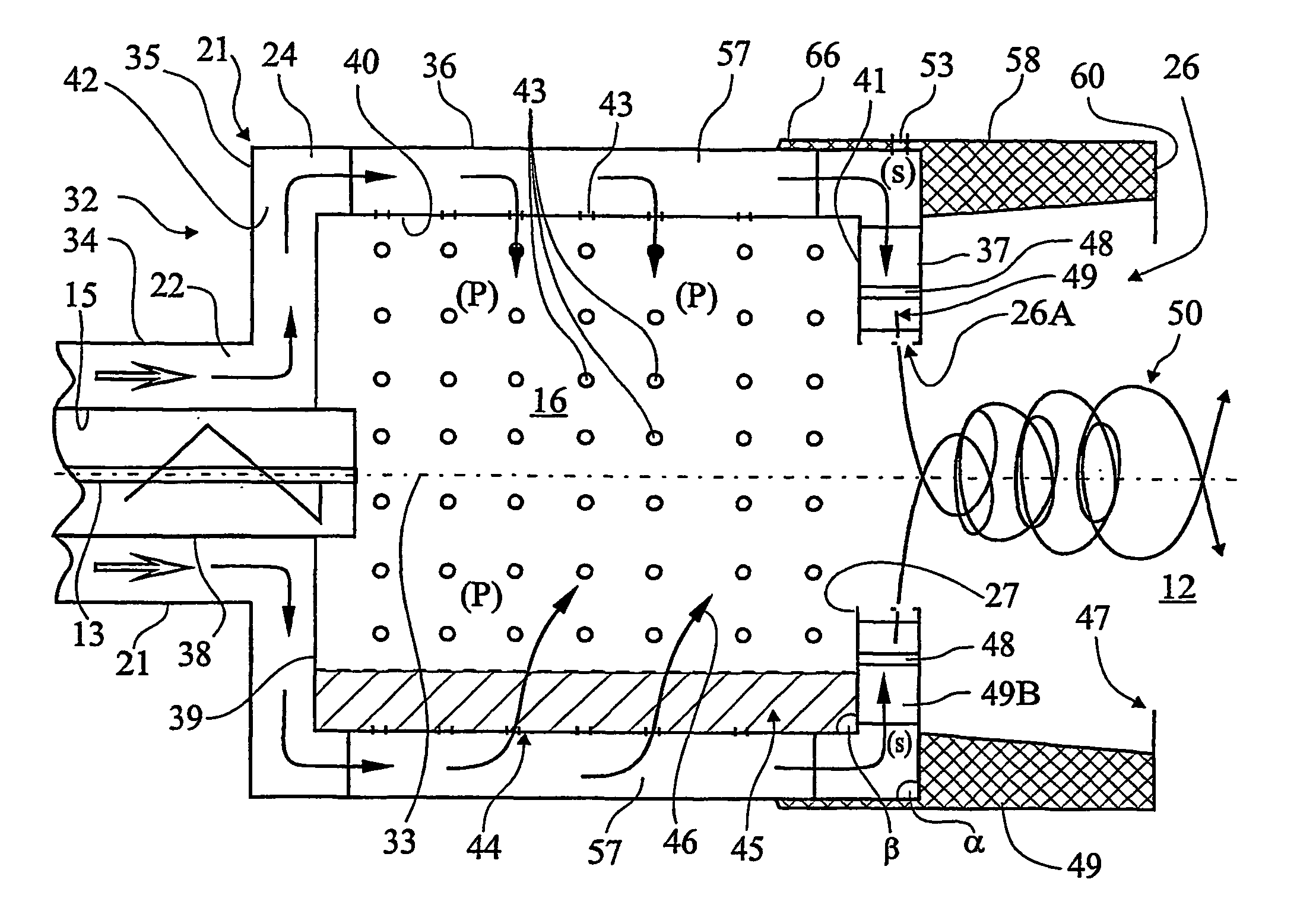
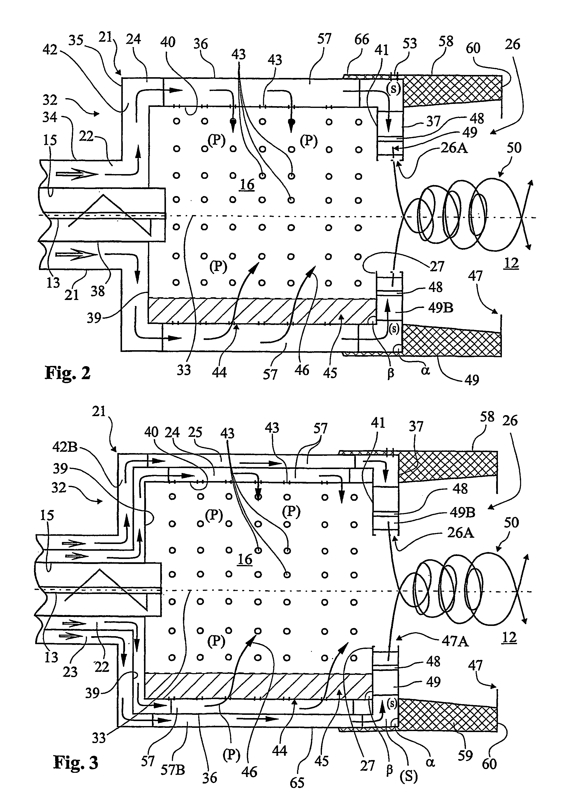
[0049]In the first embodiment, see FIG. 2, the combustion part 21 of the combustion arrangement 1 comprises the combustion chamber 16, the secondary air distributor 26A, the secondary combustion chamber 26, the fuel feed pipe 15 with the screw conveyor 13, just one common air inlet pipe 22 for both primary air (P) and secondary air (S), the air inlet pipe 22 surrounding the fuel feed pipe 15, and just one, that is to say a common chamber 24, which surrounds the combustion chamber 16, for the delivery of primary air (P) to the combustion chamber 16 and for the delivery of secondary air (S) via the secondary air distributor 26A to the secondary combustion chamber 26, furthest away from the combustion arrangement 1.

[0050]The fuel feed pipe 15, the combustion chamber 16, the secondary combustion chamber 26, the air inlet pipe 22 and the air chamber 24 preferably have an essentially circular cross-section, see FIG. 4, and the said parts 15, 16, 22, 24 are all arranged concentrically in r...

second embodiment

[0057]In the second embodiment, see FIG. 3, the combustion part 21 of the combustion arrangement 1 comprises a further two circular cylindrical and double-walled drums 23, 25. The drums 23, 25 are arranged concentrically in tandem on the outside of the air inlet pipe 22 and the air ducts or the air chamber 24 with a second, double-walled, radially circular space 42B arranged around air the inlet pipe 22, this space constituting a first part of the air chamber 25. The space 42B extends radially outwards from the said air inlet pipe 23 and connects with this pipe 23 for an even distribution of the secondary air (S) along the entire rear wall 35 of the air chamber 24. The drums 23, 25 are designed to form an outer air inlet pipe 23 and outer air ducts or air chamber 25 for delivery of secondary air (S) to the secondary combustion chamber 26 via secondary air inlet openings 48 in the secondary air distributor 26A, whilst only primary air (P) is delivered to the combustion chamber 16 via...


PUM


Abstract

The invention relates to an arrangement (1) for the combustion of granular, solid fuel, for example wood-flour pellets, chips and the like, comprising a preferably horizontal combustion chamber (16), a dispensing unit (3) for feeding the fuel into the combustion chamber via fuel feed pipe (15), air inlets (22, 23) with blower (18) for the delivery of primary air (P) to the combustion chamber via at least one air duct or air chamber (24, 25) in order to produce a flow of air through the combustion chamber and the fuel for a primary combustion of the fuel to combustion gases, and for the delivery of secondary air (S) to a secondary combustion chamber (26) via a secondary air distributor (26A) in order to produce a secondary combustion of the combustion gases formed in the primary combustion together with a common outlet (47) for the primary air, the combustion gases and the secondary air from the secondary combustion chamber to a boiler space (12) in a broiler (2) for transmitting the heat from the said primary and secondary combustion to the heat supply system of the boiler. According to the invention the secondary air distributor also comprises a fan (49) for producing an air and combustion gas vortex (50) inside the secondary combustion chamber and on out through the outlet (47) to the boiler space. The invention also relates to a method of combustion comprising such a combustion arrangement.

Description

TECHNICAL FIELD[0001]The present invention relates to an arrangement for the combustion of granular, solid fuel, for example wood-flour pellets, chips or the like, comprising a preferably horizontal combustion chamber, a dispensing unit for feeding the fuel into the combustion chamber via a fuel feed pipe, air inlets with blower for the delivery of primary air (P) to the combustion chamber via at least one air duct or air chamber in order to produce a flow of air through the combustion chamber and the fuel for a primary combustion of the fuel to combustion gases, and for the delivery of secondary air (S) to a secondary combustion chamber via a secondary air distributor in order to produce a secondary combustion of the combustion gases formed in the primary combustion, and a common outlet for the primary air (P), the combustion gases and the secondary air (S) from the secondary combustion chamber to a boiler space in a boiler for transmitting the heat from the said primary and second...

Claims


Application Information

Patent Timeline
Patent Type & Authority Patents(United States)
IPC IPC(8): F23B10/00F23D1/00F23B30/04F23G7/10F23K3/14F23L1/00F23L9/00
CPCF23B1/38F23B30/04F23L9/00F23L1/00F23G7/105F23M9/02
Inventor INGVARSSON, ROBERT
Owner SWEDISH BIOBURNER SYST
Why Eureka
Try Eureka