Fuel tank filler neck and method of manufacturing same

a technology of fuel tank and filler neck, which is applied in the direction of liquid handling, transportation and packaging, packaging goods types, etc., can solve the problems of increasing the permeability of the materials from which the fuel tank system is made, increasing the diffusion of fuel vapor, and increasing the resistance to gasoline flow. , to achieve the effect of limiting fuel vapor

Inactive Publication Date: 2006-06-13
STANT USA CORP
View PDF41 Cites 19 Cited by
  • Summary
  • Abstract
  • Description
  • Claims
  • Application Information

AI Technical Summary

Benefits of technology

[0005]The filler neck for receiving a fuel supply nozzle for a motor vehicle fuel tank includes a one-piece seamless funnel member having an integrally formed sealing surface and integrally formed threads for receiving a gas cap. The funnel member defines in off-set axial relation a relatively large inlet opening supply nozzle and a relatively small necked down outlet opening. The offset relationship of the inlet and outlet opening and tube configuration of the transition therebetween induces a swirling motion in the fuel flow as the fuel proceeds towards the fuel tank. The resultant swirl motion of the flowing fuel leaves an opening through which any pressure buildup in the fuel tank may be vented. The spiraling motion of the fuel continues through the outlet opening and into the filler tube attached thereto, further limiting fuel vapors from escaping during refueling because of an induced suctioning effect or liquid seal that is created by the spiraling motion of the fuel through the relatively narrow passage from the funnel member to the fuel tank.

Problems solved by technology

Though this approach has been somewhat successful, it is limited because as the diameter of the filler neck is decreased, the resistance to flow of the gasoline is increased.
Another design issue is the permeability of the materials from which the fuel tank system is made.
Further, such fuel vapor diffusion increases as the mild steel components corrode over time.
Another disadvantage of current filler neck design is the method by which the inlet of the filler neck is flared in order to provide a sufficient diameter to accept the gas nozzle during refueling.
Thus, through this mechanical process, there is an increasing tendency for the weld to leak as the tube is structurally weakened and thinner diameter tubes are used.

Method used


Image

  • Fuel tank filler neck and method of manufacturing same
  • Fuel tank filler neck and method of manufacturing same
  • Fuel tank filler neck and method of manufacturing same

Examples


Embodiment Construction

[0017]Reference will now be made in detail to presently preferred compositions or embodiments and methods of the invention, which constitute the best modes of practicing the invention presently known to the inventors.

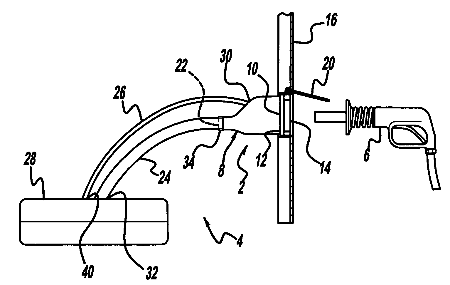
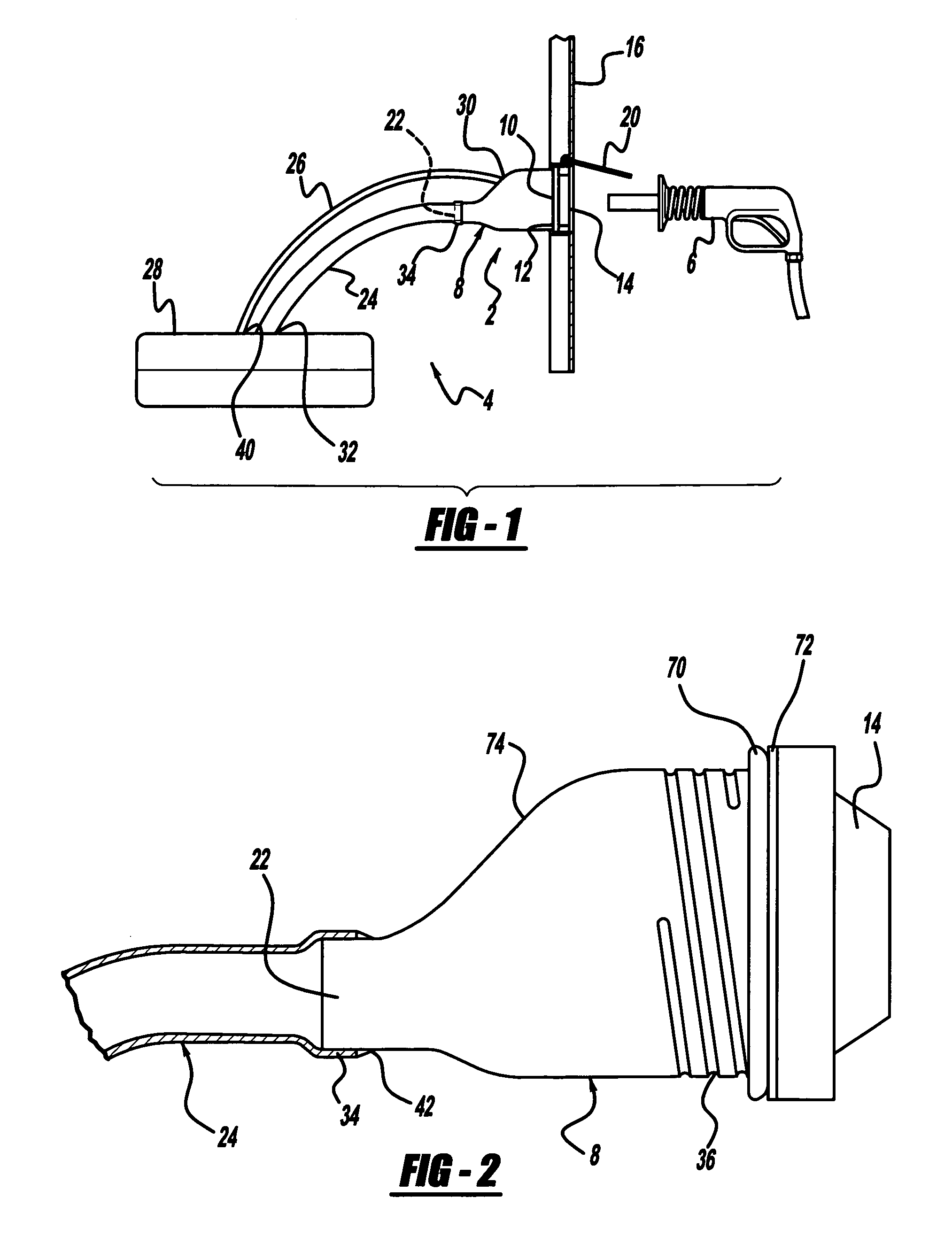
[0018]With reference to the drawings, a schematic of an embodiment of a filler neck 2 incorporated into an automobile fuel tank system 4 is provided. The fuel tank system 4 generally includes a filler neck 2, a filler tube 24, a fuel tank 28, and a gas cap 14, and is supported by an automobile body 16, which includes a movable cover 20 to conceal the gas cap 14.

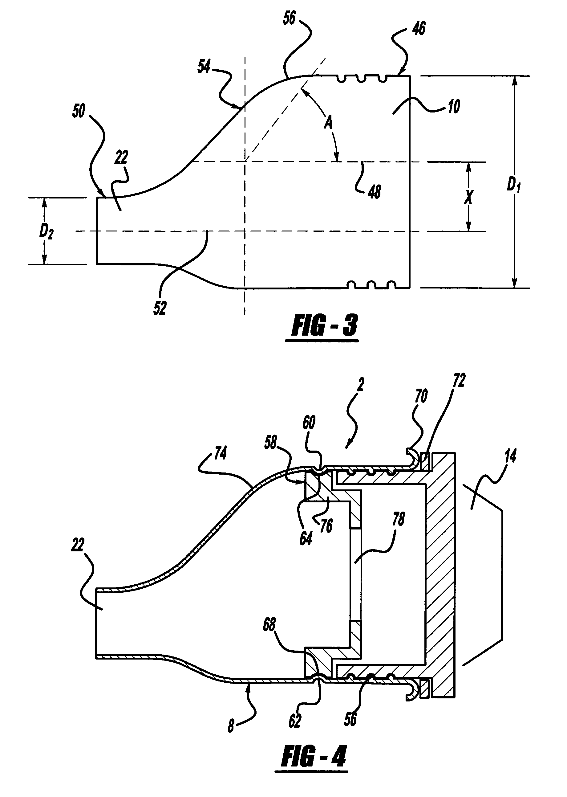
[0019]The filler neck 2 generally includes a one-piece, seamless funnel member 8 having a tubular body. The filler neck 2 may receive a nozzle receptor 12, which is an insert adapted to receive a fuel nozzle 6 during fueling. Similar filler necks are disclosed in U.S. Pat. Nos. 6,330,893 and 6,588,454, both assigned to Shelby Enterprises Inc., and expressly incorporated herein by reference.

[0020]One-piece, seamle...


PUM

PropertyMeasurementUnit
diameter D2aaaaaaaaaa

Abstract

A fuel tank filler assembly includes a filler neck configured to receive a fuel supply nozzle. The filler neck includes a one-piece seamless funnel member having a tubular body configured to swirl supplied fuel and reduce vapor escape. The tubular body includes integrally formed threads for receiving a gas cap. The funnel member defines in off-set axial relation a relatively large inlet opening adapted for attachment to a receptor for the nozzle and a relatively small necked down outlet opening adapted for attachment to the inlet of a filler tube. The filler tube is in communication with the fuel tank. A method for manufacturing the fuel tank filler neck is also disclosed.

Description

CROSS-REFERENCE TO RELATED APPLICATIONS[0001]This application is a continuation-in-part of U.S. patent application Ser. No. 10 / 615,485 filed on Jul. 8, 2003; which is a continuation of U.S. patent application Ser. No. 09 / 998,113 filed on Nov. 30, 2001 (now U.S. Pat. No. 6,588,459); which is a continuation-in-part of U.S. patent application Ser. No. 09 / 454,103 filed on Dec. 3, 1999 (now U.S. Pat. No. 6,330,893). The disclosures of the above applications are incorporated herein by reference.FIELD OF THE INVENTION[0002]The present invention relates to a fuel tank filler neck connected to a gas tank of an automobile and, in particular, to a seamless fuel tank filler neck with integral threads.BACKGROUND OF THE INVENTION[0003]Gas tank fuel systems providing reduced gasoline vapor loss are becoming increasingly important in the automobile industry to reduce needless loss of fuel. The typical solution to this problem has been to reduce the diameter of at least a section of the fuel tank fi...

Claims


Application Information

Patent Timeline
Patent Type & Authority Patents(United States)
IPC IPC(8): B65B1/04B60K15/04
CPCB60K15/04
Inventor O'CONNELL, PATRICK R.
Owner STANT USA CORP
Why Eureka
Try Eureka