Seat belt device for automobile

a seat belt and automobile technology, applied in the field of seat belts, to achieve the effect of reducing the load applied

Inactive Publication Date: 2006-06-13
HONDA MOTOR CO LTD
View PDF14 Cites 18 Cited by
  • Summary
  • Abstract
  • Description
  • Claims
  • Application Information

AI Technical Summary

Benefits of technology

[0009]In view of the above circumstances, an object of the present invention is to provide a seat belt device which enables a great reduction in the load applied to a passenger, and which can be worn without hesitation.

Problems solved by technology

Moreover, when the passenger is a woman wearing a skirt, the woman tends to hesitate to fix the self-guiding tongue plate 8, which is another problem.

Method used


Image

  • Seat belt device for automobile
  • Seat belt device for automobile
  • Seat belt device for automobile

Examples


first embodiment

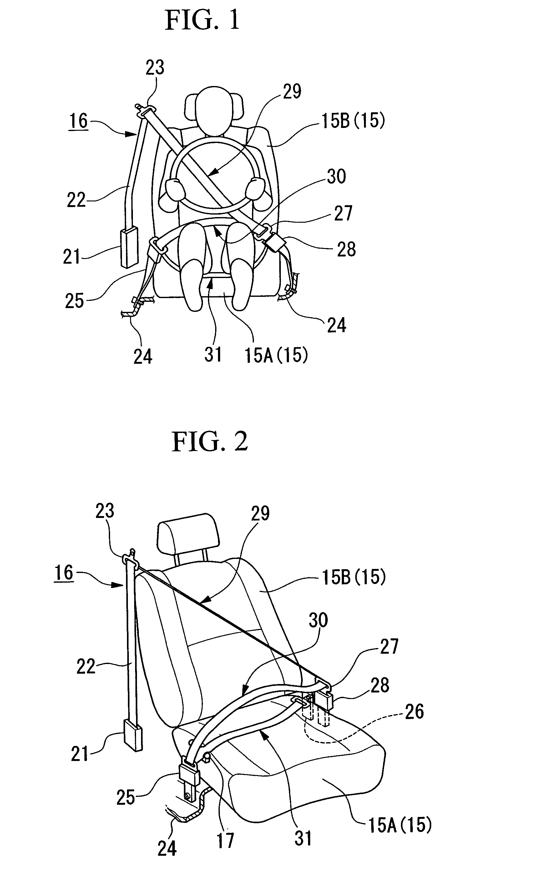
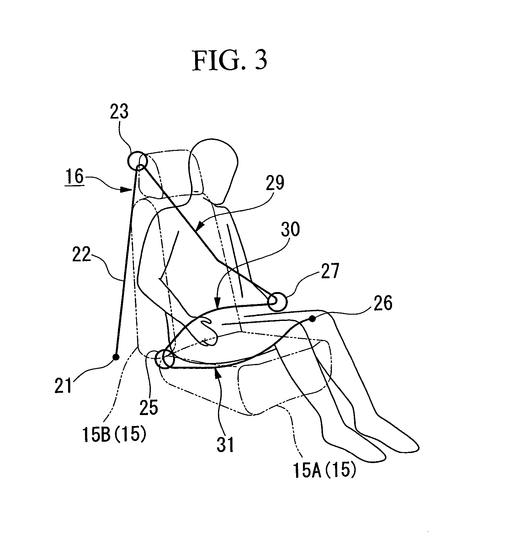
[0025]the present invention will be explained below with reference to FIGS. 1 to 3. FIG. 1 is a front view showing a state in which a passenger is seated in a driver's seat and wears a seat belt device, FIG. 2 is a perspective view showing the seat and seat belt device, and FIG. 3 is a schematic diagram showing a state in which the seat belt is being worn.

[0026]As shown in FIGS. 1 and 2, a seat 15 having a seat cushion 15A and a seatback 15B is provided with a three-point seat belt device 16. In the seat belt device 16, a seat belt 22, which is upwardly drawn from a retractor 21, is led through a through anchor 23 that is supported by a center pillar (not shown), is led through an outer through anchor 25 which is fixed to a floor 24 disposed at a position within the cabin closer to the outer side of the automobile cabin than the seat 15 (hereinafter referred to as an outer position with respect to the seat 15), and is led, as a thigh belt portion 31, above and across the seat cushio...

second embodiment

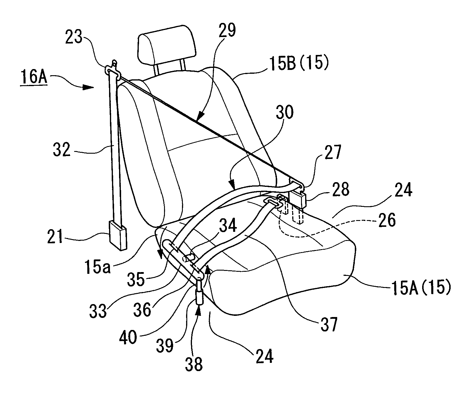
[0043]In the second embodiment, when the passenger is moving forward due to an impact while the seat belt device 16A is being worn, tension is applied to the portion of the seat belt 32 positioned between the outer anchor 33 and the retractor 21 that prohibits drawing of the seat belt 32. Upon detection of an impact force, the rod 40 in the actuator 38 projects so as to rotate the outer anchor 33 about the shaft 34 (as indicated by the arrows in FIG. 4); therefore, the thighs of the passenger are sandwiched and held between the lap belt portion 30 that is pressed downward and the thigh belt 37 that is raised upward.

[0044]Accordingly, the passenger does not feel restrained by the thigh belt 37 under normal conditions because the actuator 38 does not operate, while on the other hand, upon detection of an impact force, the load applied to the abdomen of the passenger is minimized due to the lap belt portion 30 and the thigh belt 37 so that the submarine phenomenon is prevented, and the...

third embodiment

[0053]In the third embodiment, when the passenger is moving forward due to an impact while the seat belt device 16B is being worn, tension is applied to the portion of the seat belt 42 positioned between the outer anchor 43 and the retractor 21 that prohibits drawing of the seat belt 42. The front portion of the upper half of the body of the passenger is restrained by the shoulder belt portion 29, and the thighs of the passenger is restrained by the lap belt portion 30. Upon detection of an impact force, because the pre-tensioner 44 instantly winds the thigh belt 45 as indicated by the arrow in FIG. 5, the thigh belt 45 is raised upward; therefore, the thighs of the passenger are sandwiched and held between the lap belt portion 30 and the thigh belt 45.

[0054]Accordingly, the passenger does not feel restrained by the thigh belt 45 under normal conditions because the pre-tensioner 44 does not operate, while on the other hand, upon detection of an impact force, the load applied to the ...


PUM


Abstract

A seat belt device includes a shoulder belt portion for restraining the front portion of the upper half of the body of a passenger seated in an associated seat, a lap belt portion for restraining the thighs of the passenger, and a thigh belt portion which extends across a seat cushion of the associated seat so as to be disposed under the thighs of the passenger in use, and which is provided for restraining the thighs of the passenger together with the lap belt portion.

Description

BACKGROUND OF THE INVENTION[0001]1. Field of the Invention[0002]The present invention relates to a three-point set belt device for automobiles, and in particular, relates to a seat belt device including a thigh belt.[0003]Priority is claimed on Japanese Patent Application No. 2002-297221, filed Oct. 10, 2002, the content of which is incorporated herein by reference.[0004]2. Description of Related Art[0005]Among seat belt devices for automobiles, a so-called three-point seat belt device (a lap and diagonal seat belt device) is known, which includes a shoulder belt (a diagonal belt) and a lap belt. A three-point seat belt device restrains the front portion of an upper half of the body of a passenger seated in the seat by the shoulder belt thereof, and restrains the front portion of the pelvis of the passenger by the lap belt thereof, so that the passenger is firmly restrained. Another seat belt device has been proposed, which improves the afore-mentioned seat belt device in such a man...

Claims


Application Information

Patent Timeline
Patent Type & Authority Patents(United States)
IPC IPC(8): B60R21/00B60R22/12B60R22/00B60R22/02B60R22/195B60R22/22B60R22/26B60R22/46
CPCB60R22/001B60R22/1951B60R22/02B60R22/46
Inventor HIGUCHI, HITOSHISAITO, KENICHIKAWAMURA, NOBUYUKI
Owner HONDA MOTOR CO LTD
Why Eureka
Try Eureka