Ground metal fitting and ground structure for jacks of electronic devices

a technology of electronic devices and ground fittings, which is applied in the direction of coupling protective earth/shielding arrangements, connection contact material, coupling device connections, etc., can solve the problems of troublesome ground metal fitting manufacturing, low and hamper the miniaturization of electronic devices. , to achieve the effect of improving the shielding effect of ground metal fittings and reducing clearan

Inactive Publication Date: 2006-06-13
ORION ELECTRIC CO LTD
View PDF16 Cites 11 Cited by
  • Summary
  • Abstract
  • Description
  • Claims
  • Application Information

AI Technical Summary

Benefits of technology

[0011]The present invention is to solve such problems as refereed to above. One object of the present invention is to provide a ground structure for electronic devices, capable of being fixed to an electronic device even when cylindrical portions of jacks are fitted in a resin panel, and even when intervals of the jacks are small; and capable of reducing a clearance between an outer surface of a cylindrical portion of each jack and an inner surface of a hole, in which this cylindrical portion is fitted, of a ground metal fitting, and thereby improving a shielding effect of the ground metal fitting.
[0012]A ground metal fitting for jacks of an electronic device according to the present invention comprises a front metal plate having at least a jack hole, a recess formed in at least an upper or lower portion of the jack hole, and an elongated contact member extending from a bottom portion of the recess so as to project to a position on an inner side of an inner circumference of the jack hole so that the contact member is engaged in a bent state with a cylindrical portion of a jack when fitted in the jack hole. A clearance between an inner surface of the jack hole, in which the cylindrical portion of the jack is fitted, and an outer surface of the cylindrical portion of the jack is set small so as to improve a shielding effect of the ground metal fitting.

Problems solved by technology

However, in this ground structure, a clearance “i” between an outer circumference of the cylindrical portion “e” of the jack and an inner circumference of a hole for the ground metal fitting “a” is large, so that a shielding effect of the ground metal fitting is not satisfactorily high.
. . are provided on upper, lower, left and right portions of an inner circumferential surface of the hole mentioned above, the intervals at which jacks are arranged become large, and this necessarily hampers miniaturization of the electronic device.
Since this ground metal fitting has a three dimensional solid shape having the first contact portion “f” and second contact portion “g”, manufacturing of the ground metal fitting is troublesome.
It is not easy to form the ground metal fitting to adapt to a plurality of jacks arranged on a panel of an electronic device.
However, in case the terminal panel (rear panel) is not a conductive panel, e.g. is a resin panel, it cannot be grounded.
Therefore, when jacks are provided on the front surface of a cabinet, the above-described ground structure has problems.
Thus, conventional ground structure for electronic devices have such problems as described above.

Method used


Image

  • Ground metal fitting and ground structure for jacks of electronic devices
  • Ground metal fitting and ground structure for jacks of electronic devices
  • Ground metal fitting and ground structure for jacks of electronic devices

Examples


Embodiment Construction

[0024]An embodiment of the present invention will now be described in detail on the basis of what is shown in the drawings.

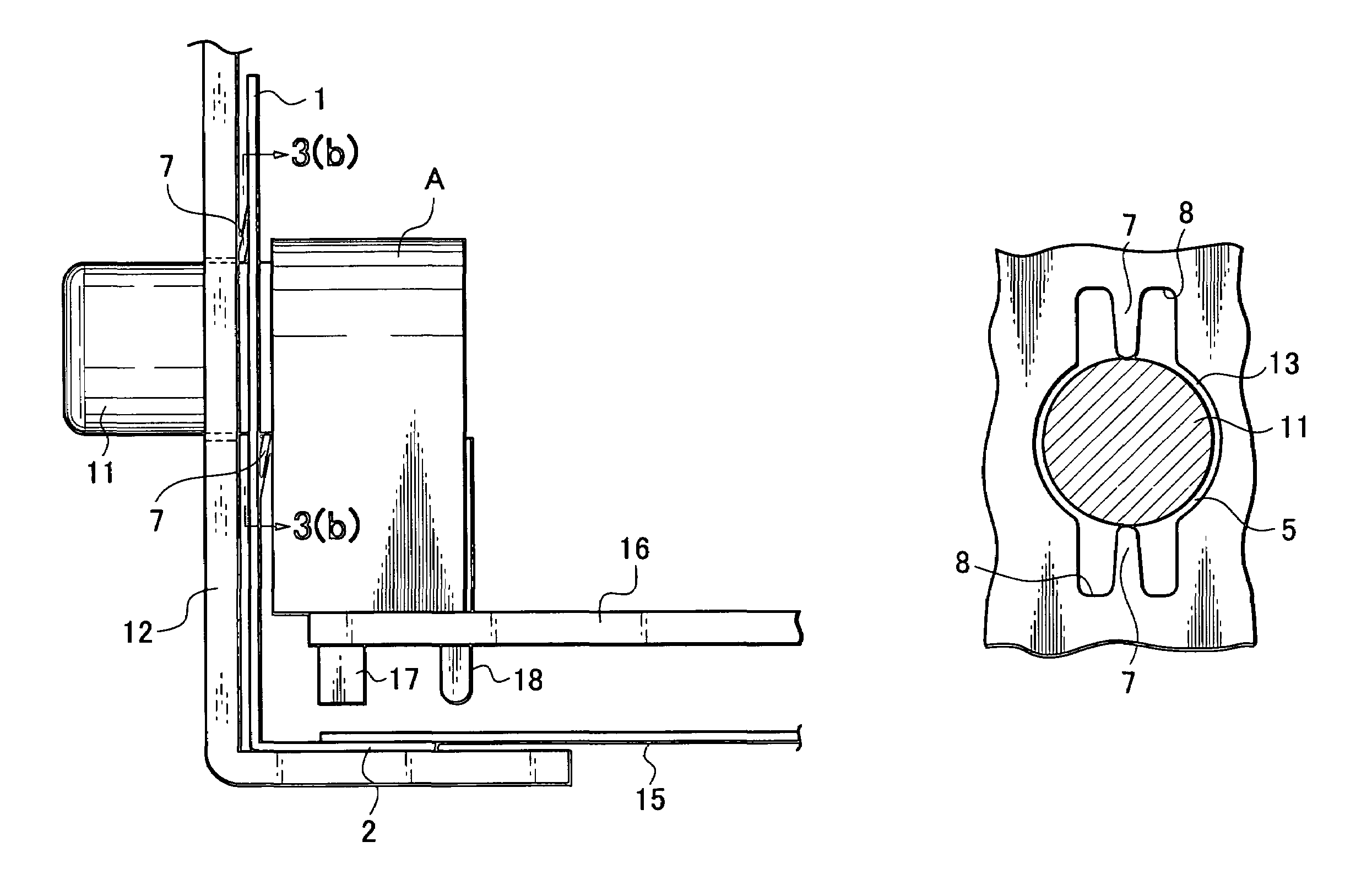
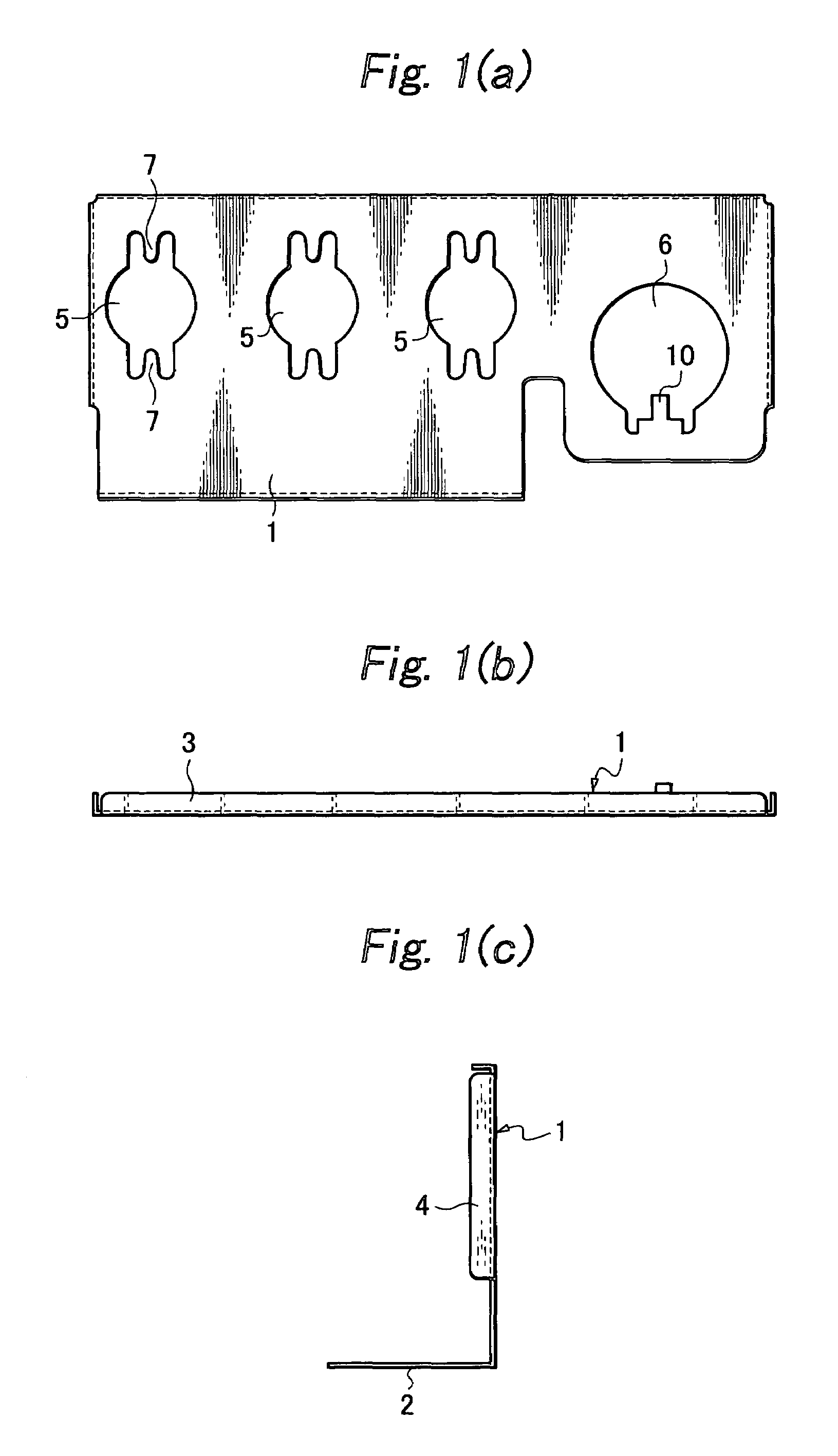
[0025]FIGS. 1(a) to 1(c) show an embodiment of a ground metal fitting according to the present invention, which is made of an L-shaped body having a substantially rectangular front plate 1 and bottom plate 2. The front plate 1 is provided at an upper edge thereof with an upper edge member 3, and at both sides thereof with side edge members 4, 4 formed so as to be bent rearward. The front plate 1 is provided with three jack holes 5 and one jack hole 6 for one jack for an S-terminal. These jack holes are provided with contact members 7, 7 respectively.

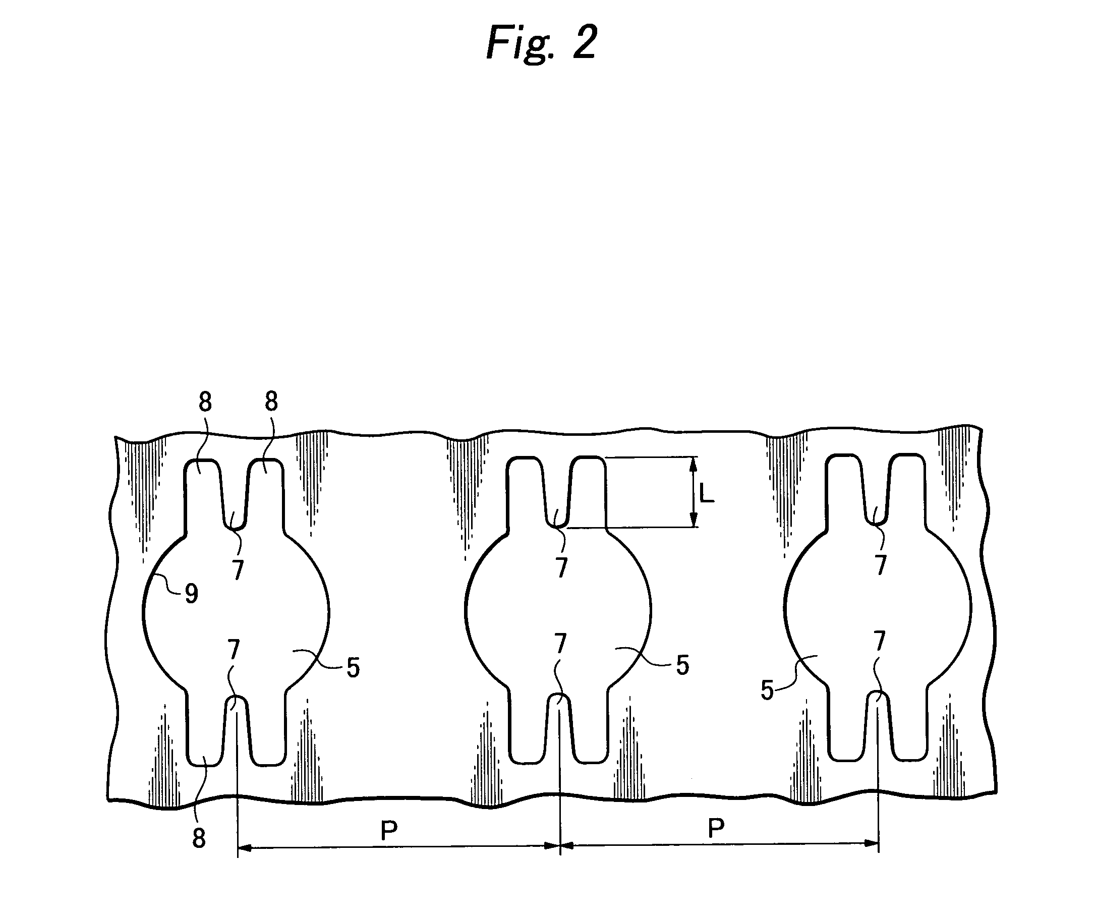
[0026]FIG. 2 shows on an enlarged scale a mode of arrangement of the jack holes 5. The jack holes 5 are arranged with a pitch P. Each jack hole 5 is provided in upper and lower portions thereof with two recesses 8, 8 respectively, and contact members 7, 7 extending toward a center of the jack hole 5 are thereby forme...


PUM


Abstract

To provide a ground structure for electronic devices, capable of being fixed to an electronic device and improving a shielding effect thereof even when a cylindrical portion of a jack is fitted in a resin panel, and even when intervals of jacks are small, a ground metal fitting has a front metal plate having at least a jack hole, a recess is formed in at least an upper or lower portion of the jack hole to form an elongated contact member extending from a bottom portion of the recess so as to project to a position on an inner side of an inner circumference of the jack hole so that the contact member is engaged in a bent state with a cylindrical portion of a jack when fitted in the jack hole.

Description

BACKGROUND OF THE INVENTION[0001]1. Field of the Invention[0002]The present invention relates to a ground metal fitting and a ground structure for jacks of electronic devices, provided so as to enable a single or plural plug or plugs to be connected to a part of an electronic device through a single or plural hole or holes made in a cabinet thereof.[0003]2. Related Art[0004]As shown in FIGS. 7(a) and 7(b), a front panel or a rear panel of an electronic device is provided with jacks for connecting the electronic device to an external electronic device. FIG. 7(a) shows jacks provided in the front panel, and FIG. 7(b) shows jacks provided in the rear panel. When the jacks are provided in the front panel, the jacks include a picture input jack “j”, left and right jacks “k”, “l” for voice input jacks, and a jack “m” for an S-terminal.[0005]On the other hand, when the jacks are provided in the rear panel, the jacks include an image input jack “j”, left and right jacks “k”, “l” for voice i...

Claims


Application Information

Patent Timeline
Patent Type & Authority Patents(United States)
IPC IPC(8): H01R4/66H01R13/655H01R13/652H01R13/658H01R13/6588H01R13/6596H01R13/73H01R13/74H01R24/38
CPCH01R4/66H01R13/6588H01R13/6596
Inventor KUNIMOTO, KAZUNORI
Owner ORION ELECTRIC CO LTD
Why Eureka
Try Eureka