
Systems and methods for conditional servowriting

a conditional servo and writing technology, applied in the field of systems and servowriting processes, can solve problems such as creating new challenges for drive manufacturers

Inactive Publication Date: 2006-06-13
WESTERN DIGITAL TECH INC
View PDF5 Cites 6 Cited by
  • Summary
  • Abstract
  • Description
  • Claims
  • Application Information

AI Technical Summary

Benefits of technology

This approach reduces position errors and improves servo performance by accurately determining the head's position relative to the track centerline, thereby minimizing written-in runout and ensuring reliable data storage.

Problems solved by technology

More narrow data tracks result in higher density drives, which is good for the consumer but creates new challenges for drive manufacturers.

Method used


Image

  • Systems and methods for conditional servowriting
  • Systems and methods for conditional servowriting
  • Systems and methods for conditional servowriting

Examples


Embodiment Construction

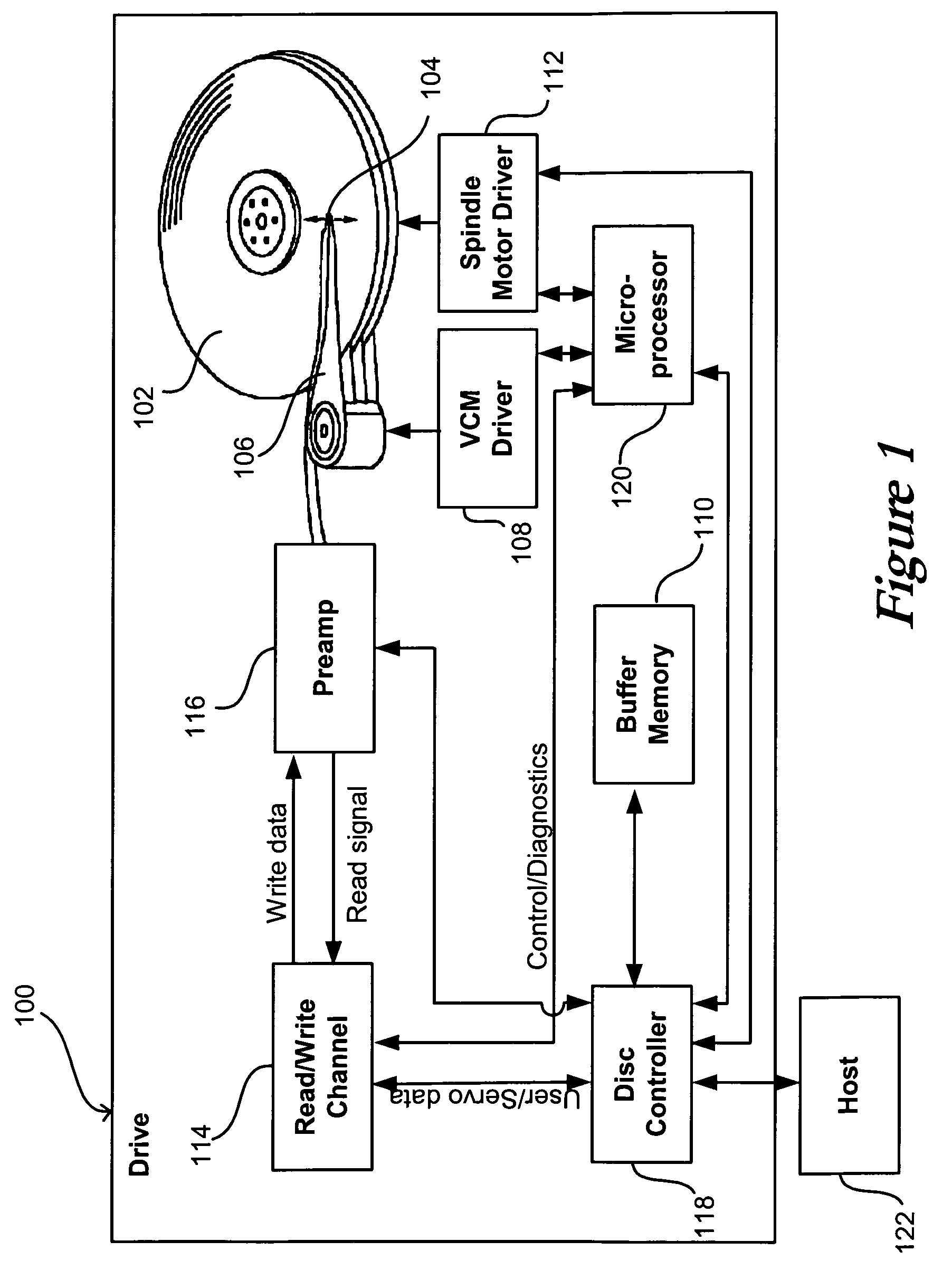
[0015]Systems and methods in accordance with various embodiments of the present invention can be used when servowriting, or self-servowriting, a rotatable storage medium in a data storage device, such as a hard disk drive. For example, a typical disk drive 100, as shown in FIG. 1, includes at least one magnetic disk 102 capable of storing information on at least one of the surfaces of the disk. A closed-loop servo system can be used to move an actuator arm 106 and data head 104 over the surface of the disk, such that information can be written to, and read from, the surface of the disk. The closed-loop servo system can contain, for example, a voice coil motor driver 108 to drive current through a voice coil motor (not shown) in order to drive the actuator arm, a spindle motor driver 112 to drive current through a spindle motor (not shown) in order to rotate the disk(s), a microprocessor 120 to control the motors, and a disk controller 118 to transfer information between the micropro...


PUM

PropertyMeasurementUnit
widthaaaaaaaaaa
densityaaaaaaaaaa
displacementaaaaaaaaaa

Abstract

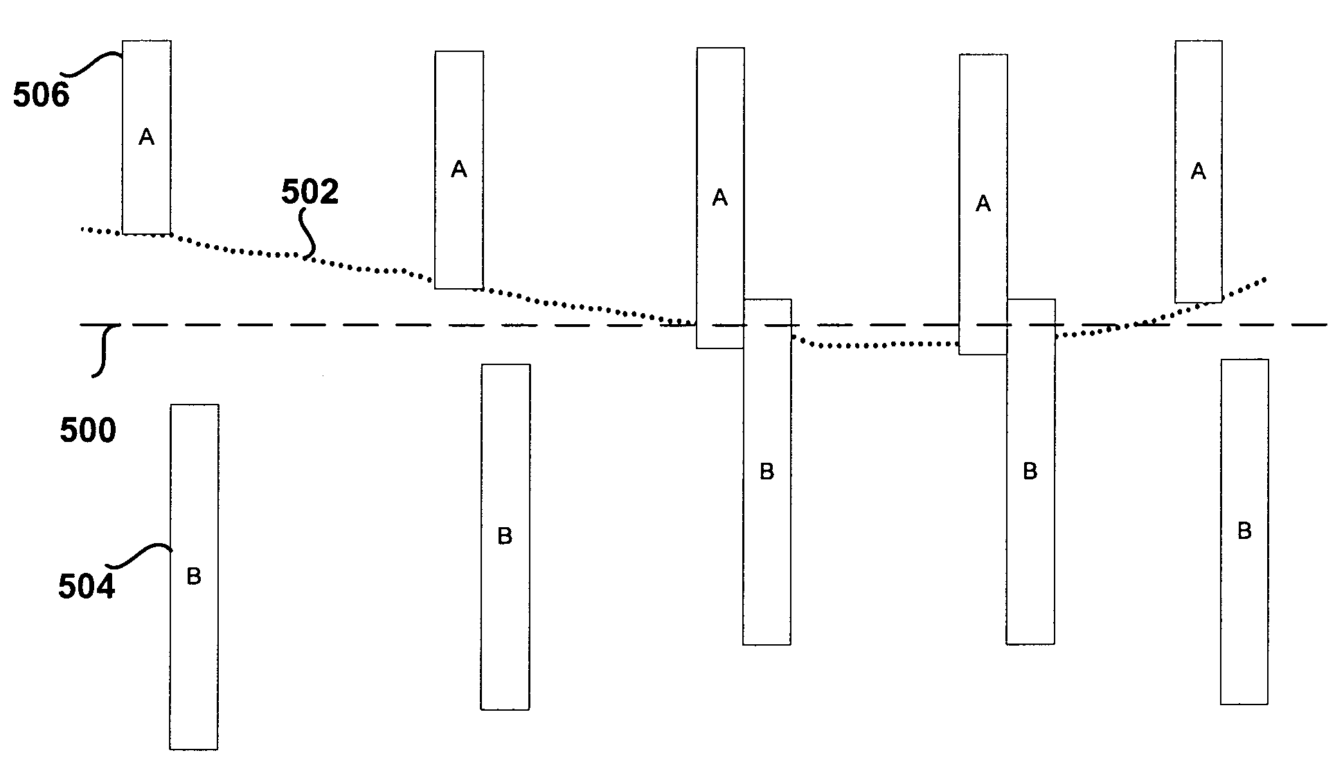
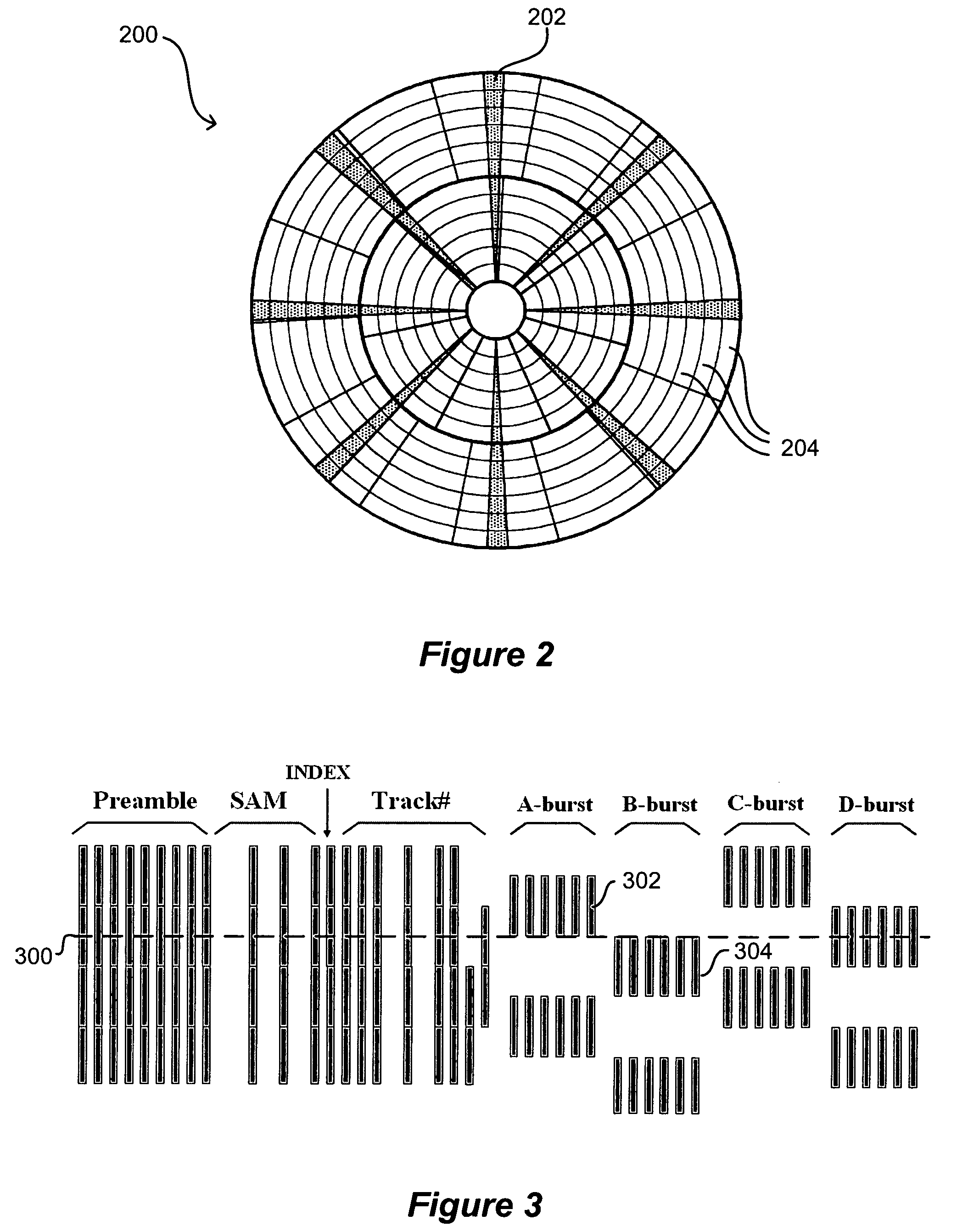
Embodiments of the present invention determine the offset of a first burst of a burst pair from a centerline. This can be used to determine the desired offset position for a second burst of the burst pair. The target signal to provided the data storage unit for writing the second burst can take into account the transfer function of the controller and the physical plant so as to more accurately write at the desired offset position.

Description

CLAIM OF PRIORITY[0001]This application claims priority to U.S. Provisional Application No. 60 / 532,429 entitled “System for Adjusting Targeting Locations in Servowriting” filed Dec. 24, 2003, and U.S. Provisional Application No. 60 / 532,589 entitled “Methods for Adjusting Targeting Locations in Servowriting” filed Dec. 24, 2003.FIELD OF THE INVENTION[0002]The present invention relates to servowriting processes, systems, and devices.BACKGROUND[0003]Advances in data storage technology have provided for ever-increasing storage capability in devices such as DVD-ROMs, optical drives, and disk drives. In hard disk drives, for example, the width of a written data track has decreased due in part to advances in reading, writing, and positioning technologies. More narrow data tracks result in higher density drives, which is good for the consumer but creates new challenges for drive manufacturers. As the density of the data increases, the tolerance for error in the position of a drive component...

Claims


Application Information

Patent Timeline
Patent Type & Authority Patents(United States)
IPC IPC(8): G11B21/02G11B5/09G11B5/596
CPCG11B5/59633
Inventor EHRLICH, RICHARD M.SCHMIDT, THORSTEN
Owner WESTERN DIGITAL TECH INC
Learn More