Color Control for Dynamic Scanning Backlight

a dynamic scanning and backlight technology, applied in the direction of electric variable regulation, process and machine control, instruments, etc., can solve the problems of motion blur, lcd matrix display, finite response time of lcd,

Active Publication Date: 2008-10-02
POLARIS POWERLED TECH LLC
View PDF29 Cites 57 Cited by
  • Summary
  • Abstract
  • Description
  • Claims
  • Application Information

AI Technical Summary

Problems solved by technology

One known problem of LCD matrix displays is motion blur.
One cause of motion blur is that the response time of the LCD is finite.
Thus, there is a delay from the time of writing to the LCD pixel until the image changes.
Furthermore, since each pixel is written once per scan, and is then held until the next scan, smooth motion is not possible.
An additional known problem of LCD matrix displays is the lack of contrast, and in particular in the presence of ambient light.
Unfortunately, a certain amount of light leakage occurs when the polarizers are oriented orthogonally to each other, thus reducing the overall contrast.
Thus, there is no opportunity to correct the LED color during a frame.
The need to generate and store predicted control information adds to cost.

Method used


Image

  • Color Control for Dynamic Scanning Backlight
  • Color Control for Dynamic Scanning Backlight
  • Color Control for Dynamic Scanning Backlight

Examples


first embodiment

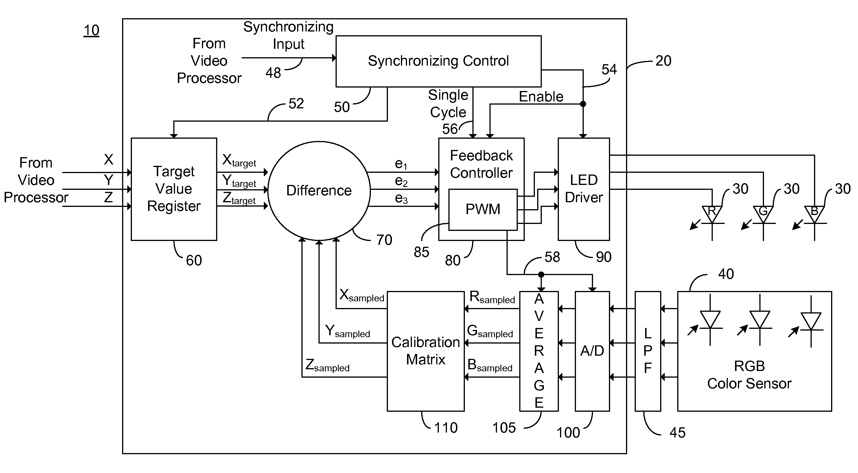
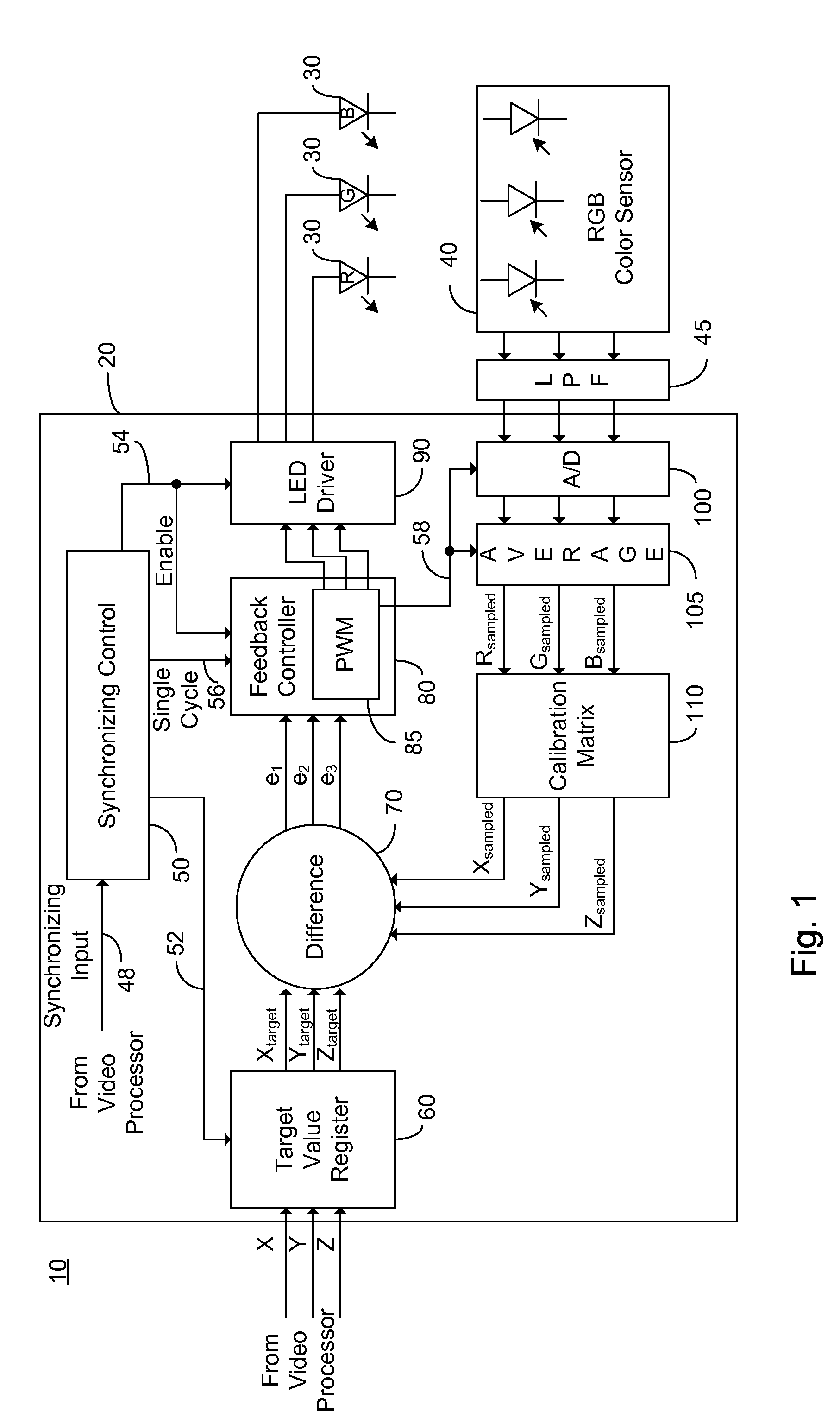
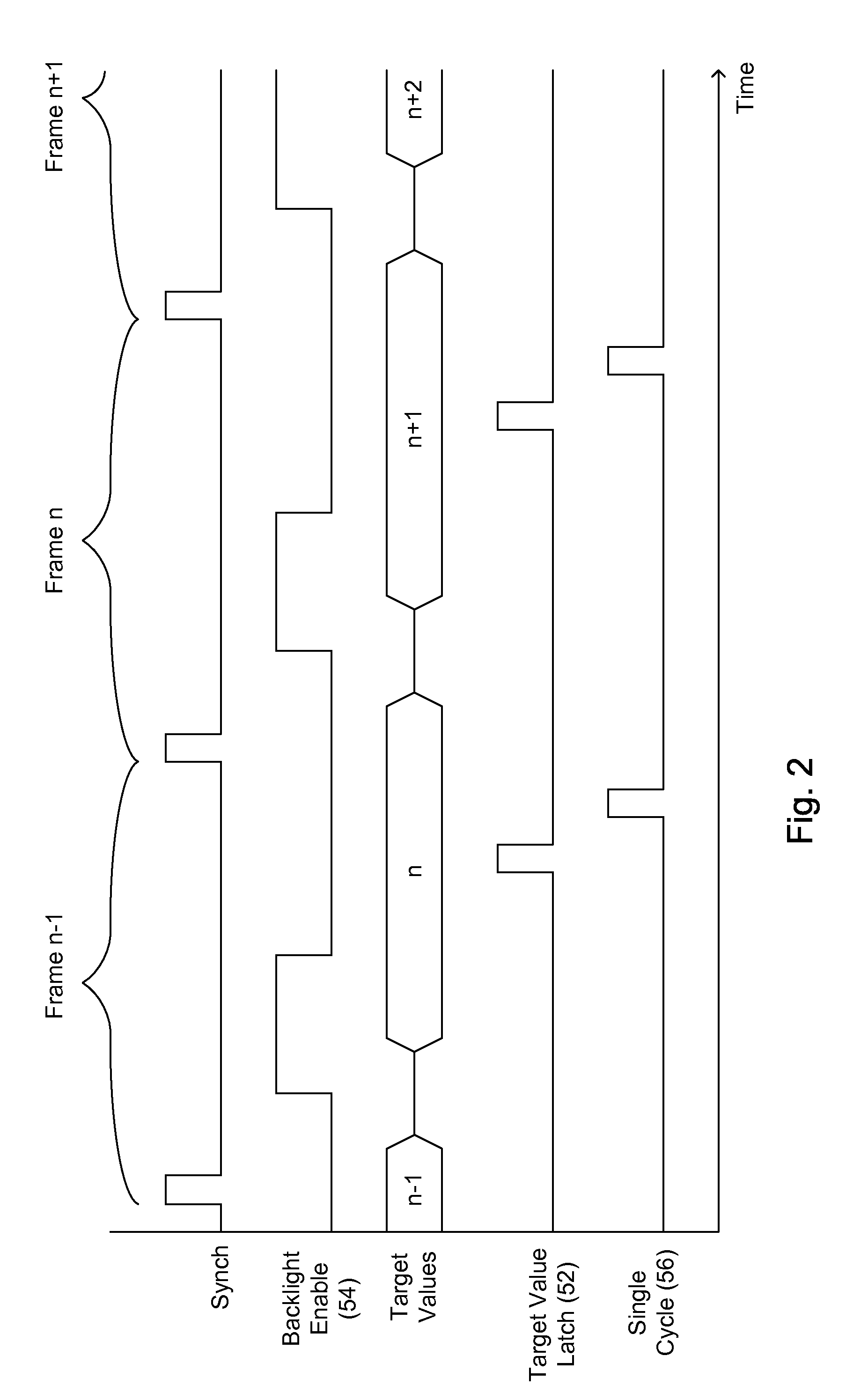
[0053]FIG. 3A illustrates a high level flow chart of the operation of the color control loop of FIG. 1 in accordance with a principle of the invention. In stage 1000, a synchronizing input signal is received at synchronizing input 48. In an exemplary embodiment the synchronizing signal is constituted of the vertical sync signal, which exhibits a pulse indicative of the beginning of a frame. In stage 1010, a first period is waited, the first period being designed to achieve the necessary delay between the received synchronizing input signal of stage 1000 and the appropriate time to enable the backlight of the subject zone. It is to be understood that for each zone a particular first period is defined, and there is no requirement for the first period to be identical across zones. In stage 1020, the backlight is enabled, preferably by setting enable output 54 of synchronizing controller 50 to active, and feedback controller 80 is enabled. In an embodiment in which feedback controller 8...

second embodiment

[0057]FIG. 3B illustrates a high level flow chart of the operation of the color control loop of FIG. 1 in accordance with a principle of the invention. In stage 2000, a synchronizing input signal constituted of a “backlight on” signal for the subject zone is received. In stage 2010, responsive to the received “backlight on” signal of stage 2000, the backlight is enabled, preferably by setting enable output 54 of synchronizing controller 50 to active, and feedback controller 80 is enabled. In an embodiment in which feedback controller 80 comprises PWM functionality 85, PWM functionality 85 is further enabled. Enabling feedback controller 80 further enables repetitive sampling of RGB color sensor 40 via A / D converter 100 and the presentation of the average of each PWM period by sample averager 105. Feedback controller 80 is operative to reduce the absolute value of error signals e1, e2, e3 toward zero.

[0058]In stage 2020, a “backlight off” signal for the present zone is received. In a...


PUM


Abstract

A method of controlling the output of a luminaire by receiving a first target signal associated with a first frame; generating a first light output control signal for an on time portion of the first frame, the light output control signal responsive to the received first target signal; sampling a light output during the on time portion of the first frame, the light output being responsive to the first light output control signal; receiving a second target signal associated with a second frame, the second frame following the first frame; comparing the received second target signal with the sampled light output of the on time portion of the first frame; and generating an error signal responsive to the comparing.

Description

CROSS-REFERENCE TO RELATED APPLICATIONS[0001]This application claims priority from U.S. Provisional Patent Application Ser. No. 60 / 908,709 filed Mar. 29, 2007, entitled “Color Control for Dynamic Scanning Backlight”, the entire contents of which is incorporated herein by reference.BACKGROUND OF THE INVENTION[0002]The present invention relates to the field of light emitting diode based lighting and more particularly to a method of improved color control for LED backlighting.[0003]Light emitting diodes (LEDs) and in particular high intensity and medium intensity LED strings are rapidly coming into wide use for lighting applications. LEDs with an overall high luminance are useful in a number of applications including backlighting for liquid crystal display (LCD) based monitors and televisions, collectively hereinafter referred to as a matrix display. In a large LCD matrix display typically the LEDs are supplied in one or more strings of serially connected LEDs, thus sharing a common cu...

Claims


Application Information

Patent Timeline
Patent Type & Authority Applications(United States)
IPC IPC(8): H05B37/02
CPCG09G3/2092G09G3/3413G09G3/3426G09G2320/064G09G2320/0666G09G2320/08G09G2360/147H05B33/0869Y02B20/341H05B45/22Y02B20/30
Inventor KORCHARZ, DRORPEKER, ARKADIYFERENTZ, ALONLANGER, TAMIR
Owner POLARIS POWERLED TECH LLC
Why Eureka
Try Eureka