Sound signal processor and delay time setting method

a delay time and sound signal technology, applied in the field of audio signal processing apparatus, can solve problems such as loudspeaker-based telephony system, call audio quality reduction, and phenomenon called howling

Inactive Publication Date: 2010-07-22
SONY CORP
View PDF4 Cites 60 Cited by
  • Summary
  • Abstract
  • Description
  • Claims
  • Application Information

AI Technical Summary

Benefits of technology

[0019]As stated above, the claimed invention can achieve an appropriate echo cancellation effect, on the occasion of echo cancellation in a loudspeaker-based telephony system, regardless of signal processing circuits located in a processing path until a first signal is emitted from a speaker and in a processing path un

Problems solved by technology

Additionally, in this regard, an increase in the sound level of the echo causes an infinite repetition of the above loop and causes a phenomenon called howling.
In this manner, the loudspeaker-based telephony system involves problems such as reduction in call audio quality due to echoes or howling and difficulty in using a call system.
Incidentally, in a case where a signal processing circuit, a transmission path, or the like is located in at least one of a signal path from an input of an echo canceller to a speaker and a signal path from a microphone to the echo canceller, a transmission delay is caused by the signal processing circuit or transmission path.
Depending on this transmission delay, a larg

Method used


Image

  • Sound signal processor and delay time setting method
  • Sound signal processor and delay time setting method
  • Sound signal processor and delay time setting method

Examples


Embodiment Construction

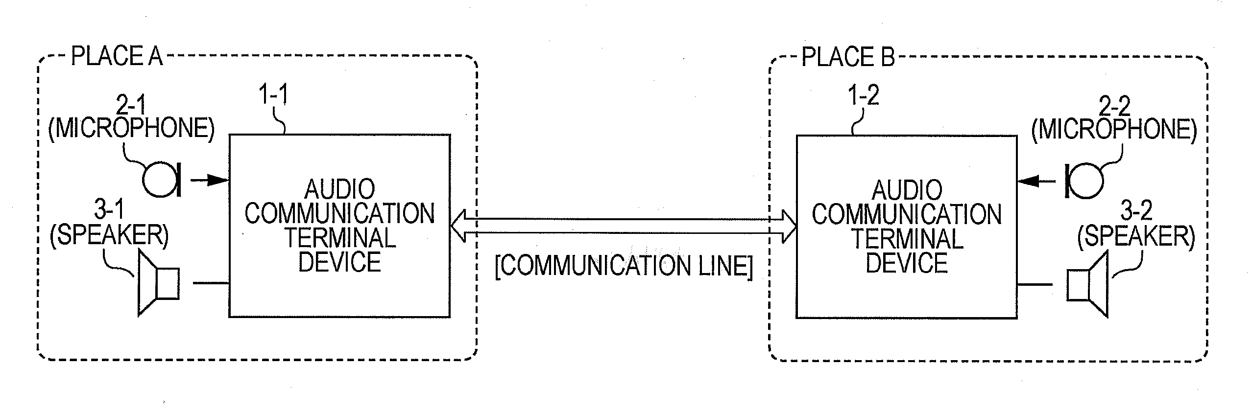
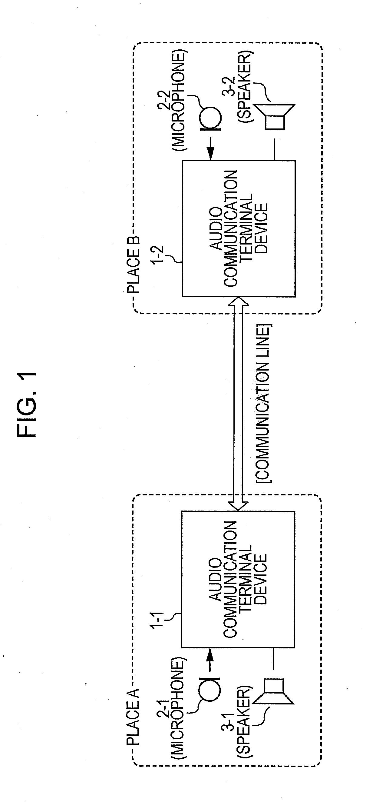
[0028]In a best mode for carrying out the claimed invention (hereinafter referred to as an embodiment), the claimed invention is applied in an audio transmission / reception system to a television conferencing system (video conferencing system).

[0029]The video conferencing system is configured such that a communication terminal device is installed at each conference room in a different place to allow this communication terminal device to transmit an image photographed by a camera device and audio picked up by a microphone to another communication terminal device and to receive an image and audio transmitted from another communication device and output them from a display device and a speaker, respectively. That is, the video conferencing system is provided with a video transmission / reception system that mutually transmits and receives an image and an audio transmission / reception system that mutually transmits and receives audio. Then, in the present embodiment, the above audio transmi...


PUM


Abstract

An echo canceller formed of an adaptive filter is designed such that even under a condition where a system transmission delay is undefined, an appropriate delay time can be set in a delay circuit that absorbs a system delay, and that an effective echo cancellation effect can always be achieved. A time difference of a transmission path until a reproduction audio signal input to the delay circuit is input as a processing target signal of an adaptive filter system through a space between a speaker and a microphone is determined, and the delay time corresponding to this time difference is set in the delay circuit. At this time, the speaker and the microphone are placed so that the distance therebetween is small, and the delay time of the delay circuit is set to 0. Thus, the determined time difference indicates a system transmission delay in the above transmission path. That is, an accurate delay time corresponding to the system transmission delay can be set in the delay circuit.

Description

TECHNICAL FIELD[0001]The present invention relates to an audio signal processing apparatus having an audio signal processing function called so-called echo cancellation, and a method for setting a delay time for a signal delay unit provided in the audio signal processing apparatus.BACKGROUND ART[0002]An acoustic system configured to provide calls, conversations, and the like between talkers present in distant places or positions in a manner as in an audio transmission / reception processing system in an audio conferencing system, a video conferencing system, and the like, as well as hands-free telephony using telephones, is also called a loudspeaker-based telephony or the like, and has already been put into practical use and widely used.[0003]In the above loudspeaker-based telephony system, for example, communication terminal devices capable of communicating with one another in accordance with a certain communication scheme are placed at a plurality of different places. In addition to...

Claims


Application Information

Patent Timeline
IPC IPC(8): H04B3/20
CPCH04M9/082H04R3/02H04B3/23H04M1/60
Inventor MATSUI, TAKESHIKATO, YASUHIKOKIHARA, NOBUYUKIKISHI, HIDEKIKODAMA, YASUHIROSAKURABA, YOHEI
Owner SONY CORP
Why Eureka
Try Eureka