
Enclosures for Containing Transducers and Electronics on a Downhole Tool

a transducer and electronics technology, applied in the field of packaging or housing, can solve the problems of affecting the mechanical complexity of the system, requiring volume compensation for oil, and not being particularly suitable or reliable for the above method

Active Publication Date: 2006-11-16
SCHLUMBERGER TECH CORP
View PDF42 Cites 56 Cited by
  • Summary
  • Abstract
  • Description
  • Claims
  • Application Information

AI Technical Summary

Problems solved by technology

A drawback with this methodology is that such implementations may require volume compensation for the oil.
Such mechanisms often entail pistons or bellows that move in response to displacement of the oil as a result of pressure and temperature changes, which then affects the mechanical complexity of the system.
However, in logging while drilling (LWD) or measuring while drilling (MWD) applications, the above methodology is not particularly suitable or reliable due to the harsh drilling environment, which may be characterized by high shock condition, high pressures and high temperatures.
Consequently, the transducers and associated electronics are typically disposed inside the drill string and are thereby isolated from the harsh drilling environment, which is detrimental to their ability to serve their intended purposes.

Method used


Image

  • Enclosures for Containing Transducers and Electronics on a Downhole Tool
  • Enclosures for Containing Transducers and Electronics on a Downhole Tool
  • Enclosures for Containing Transducers and Electronics on a Downhole Tool

Examples


Embodiment Construction

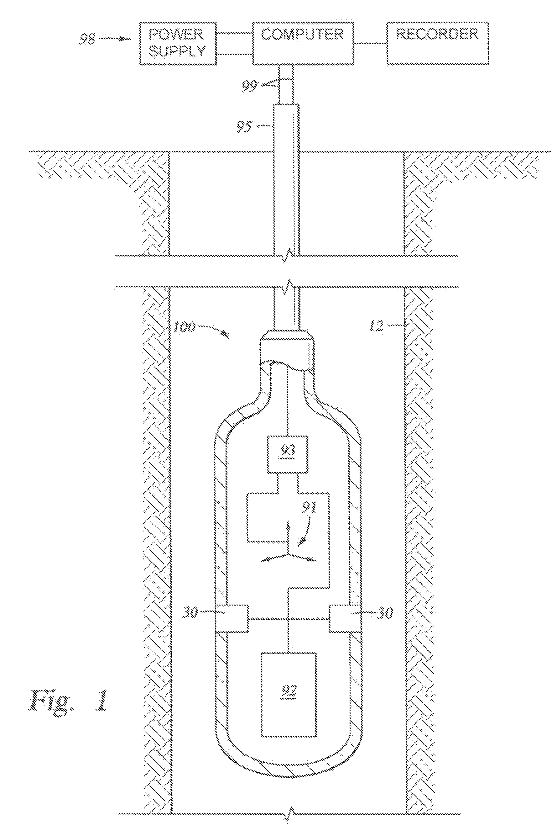
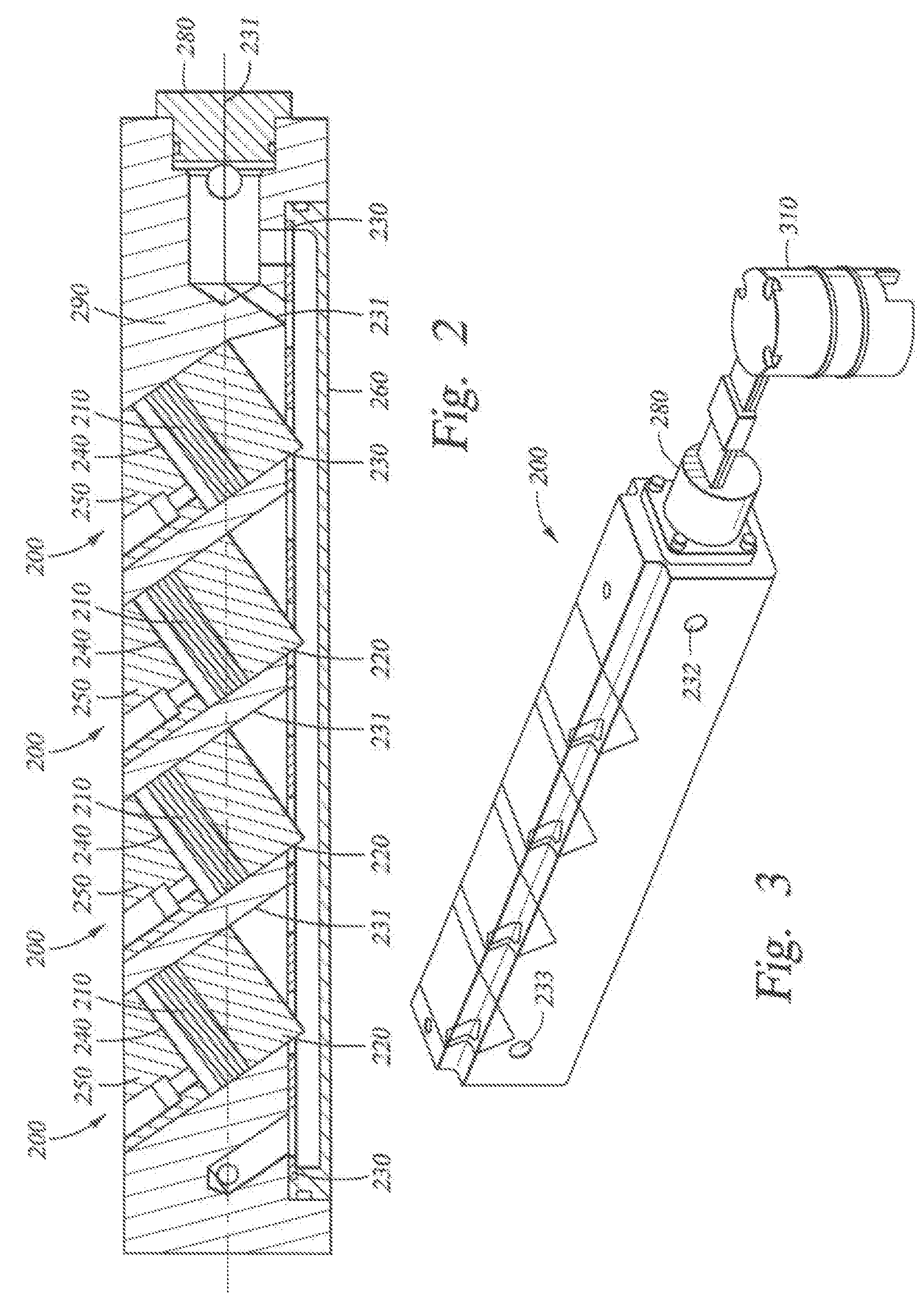
[0022]FIG. 1 illustrates a downhole tool 100 equipped with two enclosures 200, each containing transducers and electronics in accordance with implementations of various technologies described herein. Although two enclosures 30 are illustrated in the figure, it should be understood that in some implementations more or less than two enclosures may be used. The tool 100 is shown disposed in a borehole 12 that penetrates an earth formation. The enclosures 200 may be disposed on the outside surface of the downhole tool 100, which may be a drill collar, a wireline tool, casing, or any other oilfield equipment that may be deployed inside the borehole 12. The enclosure may be made from metal, plastic (e.g., polyetheretherketone PEEK® from Victrex Manufacturing Limited of Lancashire, Great Britain), or any other suitable material. Preferred materials should be strong enough to withstand the high pressures and high temperatures encountered downhole and should allow for the passage or radiatio...


PUM


Abstract

An enclosure for housing a transducer and electronics for disposal on a downhole tool. A transducer is disposed at an angle with respect to a longitudinal axis of the enclosure, wherein the enclosure contains a fluid surrounding the transducer. Enclosures also include transducers linked to motor means for selective rotation of the transducers within the enclosure. Enclosures with transducer arrays for phased or targeted signal transmission / detection.

Description

CROSS-REFERENCE TO RELATED APPLICATIONS [0001] This application claims benefit of U.S. provisional application Ser. No. 60 / 594830, filed May 10, 2005, which is herein incorporated by reference.BACKGROUND [0002] 1. Field of the Invention [0003] Implementations of various technologies described herein generally relate to the packaging or housing of various sources, sensors and electronics for use inside a wellbore. [0004] 2. Description of the Related Art [0005] The methodology of housing or packaging sources, sensors, electronics, and general components has seen many changes as technologies and materials have improved over time. In the oil and gas industry, subsurface formations are typically probed by well logging instruments to determine the formation characteristics. Data is typically acquired using sources and sensors disposed on a downhole tool and either stored in downhole memory or transmitted to the surface. As used herein, the term “transducers” is understood to encompass de...

Claims


Application Information

Patent Timeline
IPC IPC(8): E21B47/00
CPCG01V1/52
Inventor PABON, MIGUEL F.OSUNA, FERNANDO GARCIAAYERS, DAVID B.
Owner SCHLUMBERGER TECH CORP
Learn More