Surface light field decomposition using non-negative factorization

a technology of surface light field and non-negative factorization, which is applied in the field of compressing graphical data for threedimensional objects, can solve the problems of difficult development, inaccurate techniques, and difficult implementation on traditional graphics hardwar

Inactive Publication Date: 2006-06-13
INTEL CORP
View PDF7 Cites 37 Cited by
  • Summary
  • Abstract
  • Description
  • Claims
  • Application Information

AI Technical Summary

Problems solved by technology

However these techniques can be inaccurate, are difficult to implement on traditional graphics hardware, and are challenging to develop.
However the amount of data associated with such models is enormous.
This significantly limits their use, since storage, data transmission, and rendering suffer as a result of the large size of these models.
Some approaches interpolate between two related images to reduce the amount of data required, however this approach does not significantly reduce the amount of data needed, and many images are still required to display visually-realistic objects.

Method used


Image

  • Surface light field decomposition using non-negative factorization
  • Surface light field decomposition using non-negative factorization
  • Surface light field decomposition using non-negative factorization

Examples


Embodiment Construction

[0019]In the following description, for the purpose of explanation, numerous specific details are set forth in order to provide a thorough understanding of the present invention. It will be apparent, however, to one skilled in the art that the present invention may be practiced without some of these specific details. In other instances, well-known structures and devices are shown in block diagram form.

[0020]The present invention includes various steps, which will be described below. The steps of the present invention may be performed by hardware components or may be embodied in machine-executable instructions, which may be used to cause a general-purpose or special-purpose processor or logic circuits programmed with the instructions to perform the steps. Alternatively, the steps may be performed by a combination of hardware and software.

Displaying an Approximate Representation of an Object

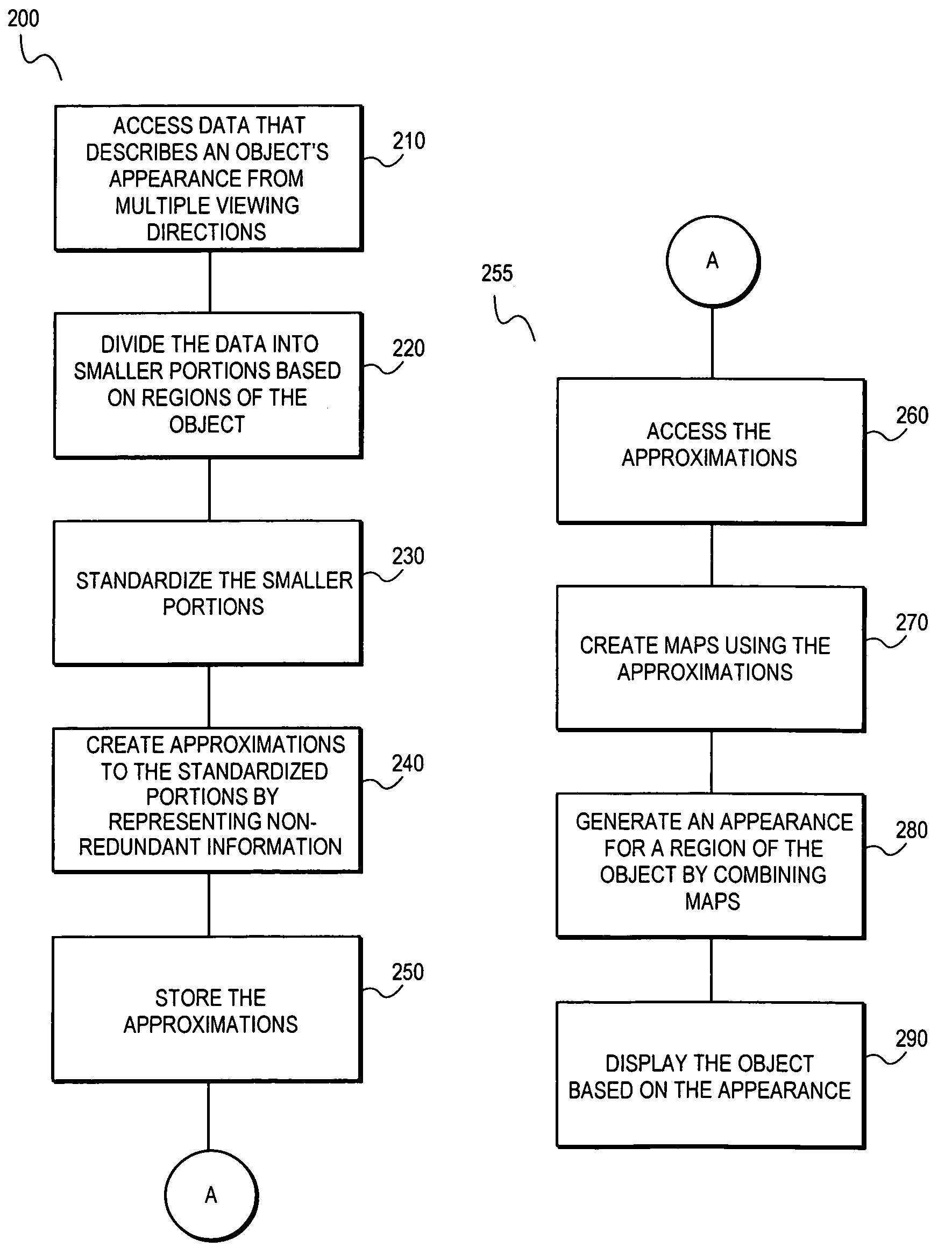
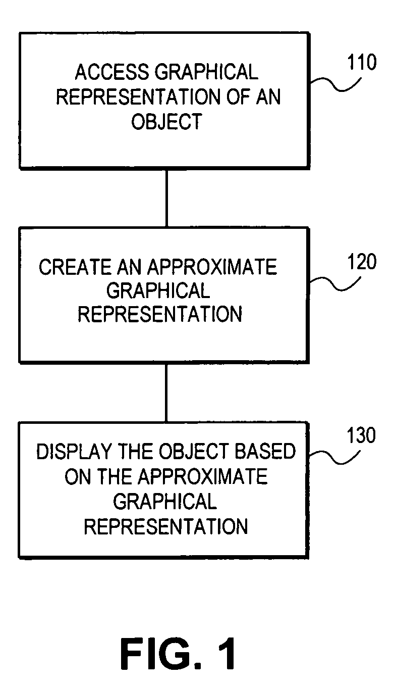
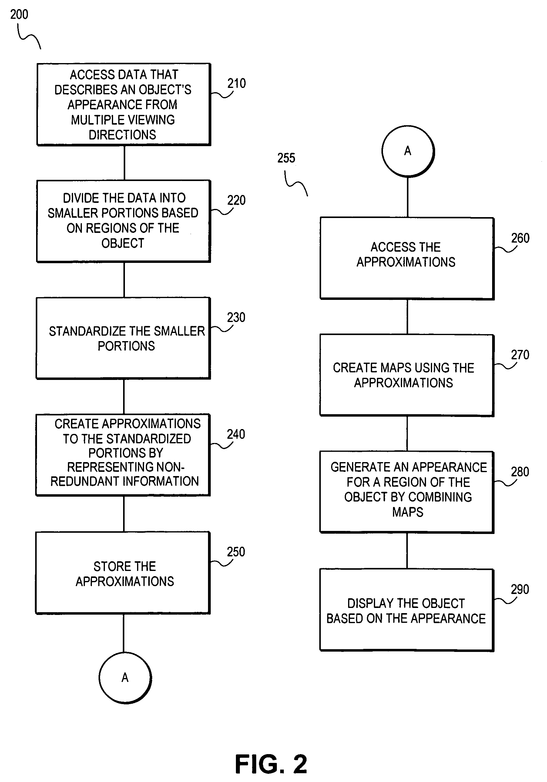
[0021]FIG. 1 shows a method for displaying an object using an approximate graphical representat...


PUM


Abstract

A system and method are provided for compressing a graphical representation that describes the appearance of an object from a plurality of viewing directions. Compressing includes accessing the graphical representation, removing redundant descriptive information from the graphical representation using sign consistent matrix factorization and approximation techniques, and representing the remaining information for efficient rendering, such as rendering with hardware-assisted computation.

Description

BACKGROUND OF THE INVENTION[0001]1. Field of the Invention[0002]The invention relates generally to compressing graphical data for three-dimensional objects. More particularly, the invention relates to a system and method for efficiently compressing graphical data that describes the appearance of a three-dimensional object from multiple viewing directions.[0003]2. Background Information[0004]Accurate portrayal of the physical world has been an important goal of computer graphics since its inception. This includes modeling the geometry and surface attributes of the object when the object is illuminated by a light source and viewed in a virtual environment from a certain vantage point. Typically, the geometry is modeled as a polygonal mesh that models the geometric extents of the object. The surface attributes, which can be modeled in a number of ways, are then applied to the geometry during rendering to graphically display the object.[0005]The essential part of the quest for realistic...

Claims


Application Information

Patent Timeline
Patent Type & Authority Patents(United States)
IPC IPC(8): G06F17/10G06F17/16G06T9/00G06T9/20
CPCG06F17/16G06T9/20G06T9/00
Inventor GRZESZCZUK, RADEKBOUGET, JEAN-YVESCHU, MICHAEL H.
Owner INTEL CORP
Why Eureka
Try Eureka