
Tonal rotors

a technology of rotors and rotors, applied in the field of methods, systems and apparatus for managing digital communication systems, can solve the problems of limited computational error, complex local updates (that is, updates performed within a modem or other communication line device), and achieve the effects of saving computational complexity, cost of implementation, and limited computational errors

Inactive Publication Date: 2006-11-16
ASSIA SPE LLC CO THE CORP TRUST CO
View PDF13 Cites 26 Cited by
  • Summary
  • Abstract
  • Description
  • Claims
  • Application Information

AI Technical Summary

Benefits of technology

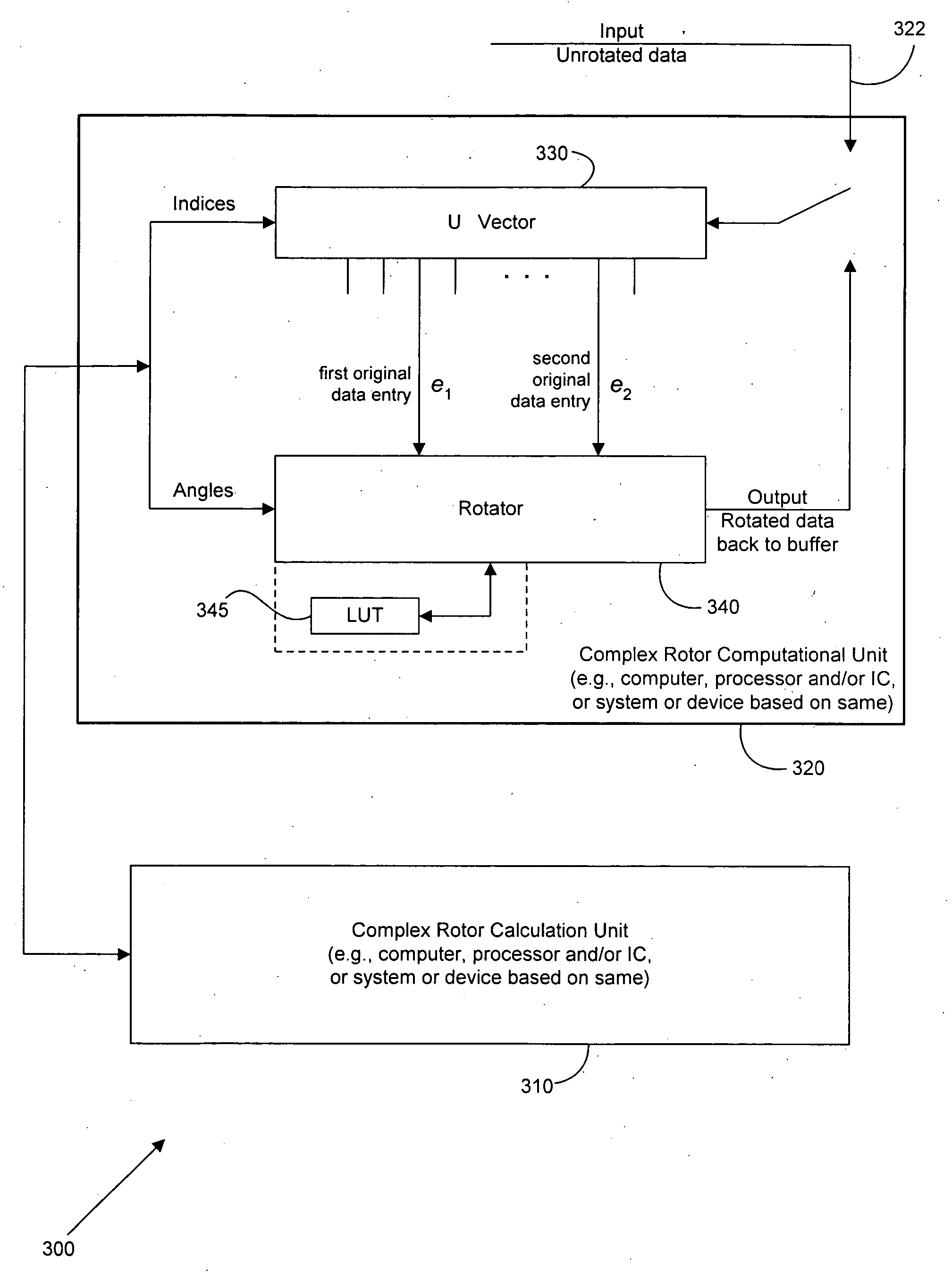
[0013] The present invention assists in the efficient implementation of any unitary “Q” matrix in a QR or other sophisticated matrix factorization (for example, like singular-value decomposition or MMSE-GDFE calculations as described in Chapter 5 of Digital Data Transmission by John M. Cioffi) that characterizes vector DMT DSLs and copper transmission systems (such as perhaps also 10Gbps Ethernet transmission systems). A complex form of the so-called “Givens” implementation of the Q matrix is characterized in the invention in terms of a sequence of complex rotations that are implemented using a complex rotor computational unit. This complex rotor computational unit accepts a minimum of two real angles and a pair of integer indices for each of a set of successive complex rotor calculations and then implements the complex rotation as a series of a minimum of three real rotations with one real angle used twice and the other real angle used once, providing two complex outputs (that is, two rotated data entries from a data vector comprising indexed communication data) for two complex inputs (two original data entries from a data vector comprising indexed communication data). The index-angle sets for each successive rotation can be provided by a complex rotor calculation unit, which may be collocated with the complex rotor computational unit, located in a controller such as a DSL optimizer, or located in any other suitable device or apparatus that has performed the QR factorization upon supplied matrix multiple input-multiple output (“MIMO”) transfer functions for the vectored channel.
[0014] Rotations that are deemed (on all angles) to be sufficiently close to zero in angle measure may be ignored by the complex rotor computational unit (or not provided by the complex rotor calculation unit or any controller controlling operation of the complex rotor calculation unit) to save computational complexity, which enables the designer of an implementation to gauge the number of implemented rotations to the cost of implementation. The Q (or Q*) matrix can be updated by the complex rotor calculation unit (for example, in a DSL optimizer or other controller in a DSL or other communication system), recognizing that local updates (that is, updates performed within a modem or other communication line device) typically are complicated and limited by computational error. In such cases, the overall order of rotation may be best decided by a search procedure that is implemented centrally with the cost shared by the various lines serviced by the complex rotor calculation unit, controller and / or DSL optimizer.

Problems solved by technology

The Q (or Q*) matrix can be updated by the complex rotor calculation unit (for example, in a DSL optimizer or other controller in a DSL or other communication system), recognizing that local updates (that is, updates performed within a modem or other communication line device) typically are complicated and limited by computational error.

Method used


Image

  • Tonal rotors
  • Tonal rotors
  • Tonal rotors

Examples


example

[0065] Let Q be represented by a data structure which includes L sets. Each set corresponds to a row of the sparse matrix Q. Each set contains a number of pairs (col, val), where col defines the column of a non-zero element at a given row, and val corresponds to the value of this non-zero element.

[0066] Letting y=Q*x be the vector output, then the computation of the value for a specific row of y can be written as:

y[row]=0

for each pair (col, val) in set corresponding to row,

y[row]=y[row]+val*x[col]

end

[0067] Thus the number of operations can be significantly reduced for sparse matrices. Such methods can be applied in a straightforward way for any MIMO processing in a vectored transmitter or vectored receiver.

[0068] Each tone can use a tonal complex rotor computational unit such as the one shown in FIG. 3 (which again could be a single unit shared by all). The input vector may be stored initially in a vector register. A high-speed two-dimensional rotation is executed several tim...


PUM


Abstract

A set of complex rotations are used to implement a unitary “Q” matrix that can arise in various transmitters and / or receivers in communication line vectoring. Each complex rotation is a set of real rotations, where the minimum number of real rotations to perform the complex rotation is three, and where the minimum number of angles to characterize the real rotations is two. An order of rotations is also provided. The invention assists in the efficient implementation of any unitary “Q” matrix in a QR or other sophisticated matrix factorization. A complex form of the so-called “Givens” implementation of the Q matrix is characterized in terms of a sequence of complex rotations that can implemented using a complex rotor computational unit that accepts a minimum of two real angles and a pair of integer indices for each of a set of successive complex rotor calculations and then implements the complex rotation as a series of a minimum of three real rotations with one real angle used twice and the other real angle used once, providing two complex outputs (that is, two rotated data entries from a data vector comprising indexed communication data) for two complex inputs (two original data entries from a data vector comprising indexed communication data). The index-angle sets for each successive rotation can be provided by a complex rotor calculation unit, which may be collocated with the complex rotor computational unit, located in a controller such as a DSL optimizer, or located in any other suitable device or apparatus that has performed the QR factorization upon supplied matrix MIMO transfer functions for the vectored channel.

Description

CROSS-REFERENCE TO RELATED APPLICATIONS [0001] This application claims the benefit of priority under 35 U.S.C. § 119(e) of the following: [0002] U.S. Provisional No. 60 / 679,621 (Attorney Docket No. 0101 -p16p) filed on May 10, 2005, entitled TONAL ROTORS, the entire disclosure of which is incorporated herein by reference in its entirety for all purposes. [0003] U.S. Provisional No. 60 / 698,113 (Attorney Docket No. 0101-p28p) filed on Jul. 10, 2005, entitled DSL SYSTEM, the entire disclosure of which is incorporated herein by reference in its entirety for all purposes.STATEMENT REGARDING FEDERALLY SPONSORED RESEARCH OR DEVELOPMENT [0004] Not applicable. REFERENCE TO SEQUENCE LISTING, A TABLE, OR A COMPUTER PROGRAM LISTING COMPACT DISK APPENDIX [0005] Not applicable. BACKGROUND [0006] 1. Technical Field [0007] This invention relates generally to methods, systems and apparatus for managing digital communication systems. [0008] 2. Description of Related Art [0009] Digital subscriber line...

Claims


Application Information

Patent Timeline
IPC IPC(8): G06F7/52H04J99/00
CPCG06F17/16H04L5/023H04L2025/0349H04L25/03343H04L2025/03414H04L25/0246
Inventor CIOFFI, JOHN M.ALMANDOZ, IKERGINIS, GEORGIOS
Owner ASSIA SPE LLC CO THE CORP TRUST CO
Learn More