Mower attachment mechanism

a technology of attachment mechanism and mower, which is applied in the direction of mower, mower, agriculture tools and machines, etc., can solve the problems of serious distribution problems for users, air flow “swirling around” the inside of the housing, and grass clippings not being quickly and/or directly flowing through the discharge chute, etc., and achieves efficient direction

Active Publication Date: 2006-06-20
WOODS EQUIP
View PDF34 Cites 28 Cited by
  • Summary
  • Abstract
  • Description
  • Claims
  • Application Information

AI Technical Summary

Benefits of technology

[0005]It is therefore an object of the invention to provide an improved system for cutting grass, wherein air flow is more efficiently directed through the system than in conventional devices.
[0006]It is another object of the present invention to provide an improved system for cutting grass where a reduced number of grass clippings are misdirected after being cut.
[0007]In accordance with the above objects, there is provided a mower attachment comprising an attachment housing and a plurality of blade assemblies. The attachment housing includes an upper surface, as well as front and rear baffles extending downwardly therefrom to define a plurality of blade chambers. The plurality of blade assemblies are positioned within the plurality of blade chambers and are arranged to effectively cut or mow grass. A leading plate is operatively connected to the front of the housing extending away from the plurality of blade chambers. The leading plate includes a plurality of apertures on one side thereof. The plurality of apertures are arranged such that during the cutting process, air flows through the plurality of apertures to aid in the directing of grass clippings through the discharge chute.
[0008]The use of this “false front” on the mower attachment enhances the blade suction while at the same time providing structural integrity and better air flow, controlling “blow out” of the system. The “false front” also creates a vacuum in the blade chambers that is distributed uniformly by the plurality of holes to lift the grass prior to being cut.

Problems solved by technology

Although such mowing systems are widely used, conventional systems include a number of drawbacks.
For example, the air flow through the attachment system during the mowing process is quite inefficient in that the air flow is inefficiently directed inside the housing resulting in some of the air flow “swirling around” the inside of the housing.
This causes some of the grass clippings to not quickly and / or directly flow through the discharge chute.
All of these actions cause serious distribution issues for the user, as the amount of time needed to distribute all of the grass clippings increases substantially due to this inefficient air flow.

Method used


Image

  • Mower attachment mechanism
  • Mower attachment mechanism
  • Mower attachment mechanism

Examples


Embodiment Construction

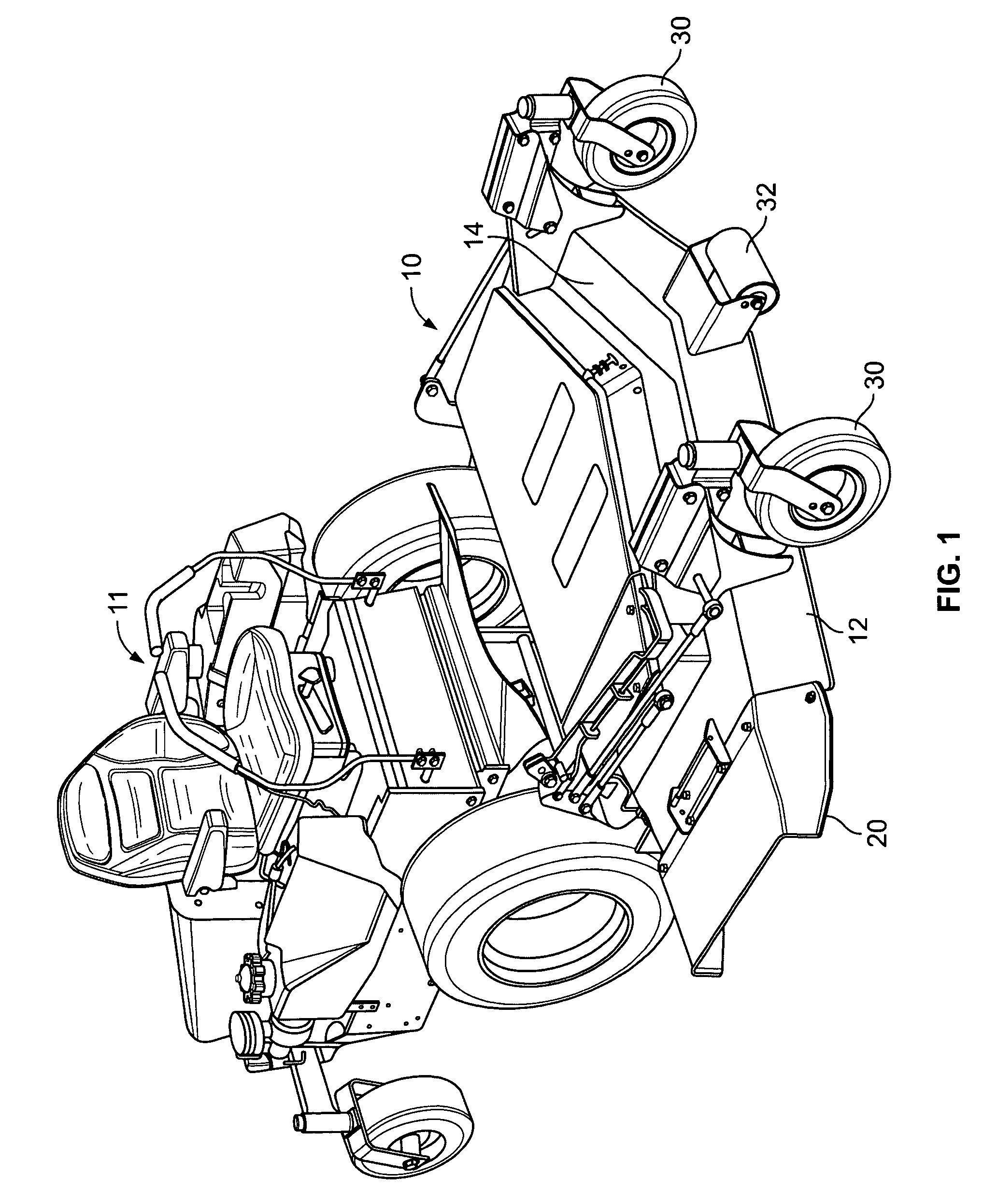
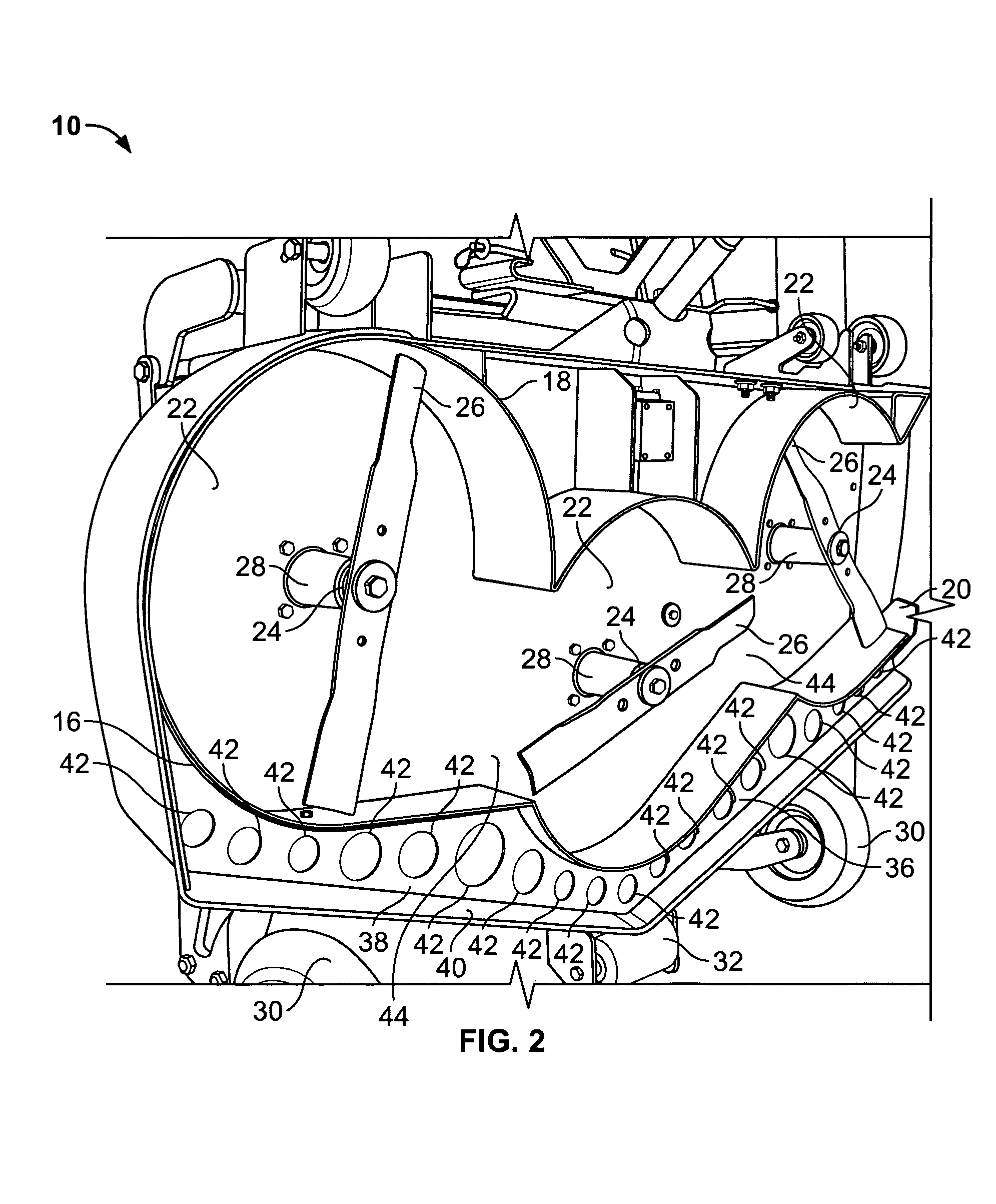
[0015]A mower attachment unit is shown generally at 10 in FIGS. 1–4. In FIG. 1, the mower attachment unit is operatively connected to a tractor 11 for use in operating and moving the mower attachment unit 10. The mower attachment unit 10 comprises an attachment housing 12 including an upper surface 14, as well as a front baffle 16 and a rear baffle 18. The front baffle 16 and the rear baffle 18 can either be formed as one piece with the upper surface 14 or can be formed as separate components that are coupled to the upper surface 14 by a plurality of fasteners. Additionally, it is possible for the front baffle 16 and the rear baffle 18 to be formed as a single piece. A discharge chute 20 is located on one side of the attachment housing 12. When the mower attachment unit 10 is in use, grass clippings that have already been cut are expelled through the discharge chute 20.

[0016]The front baffle 16 and the rear baffle 18 combine to define a plurality of blade chambers 22 therebetween. I...


PUM


Abstract

A mower attachment comprising an attachment housing and a plurality of blade assemblies. The attachment housing includes an upper surface and front and rear baffles extending downwardly from the upper surface, the front and rear baffles shaped to define a plurality of blade chambers therebetween. The plurality of blade assemblies are positioned within the plurality of blade chambers. A leading plate is operatively connected to the housing and extends away from the plurality of blade chambers. The leading plate includes a plurality of apertures on a top side thereof.

Description

FIELD OF THE INVENTION[0001]The present invention relates generally to systems for cutting grass. More particularly, the present invention is directed to systems for cutting or mowing grass involving the use of a mower attachment including a plurality of blade assemblies.BACKGROUND OF THE INVENTION[0002]A wide variety of systems are conventionally known for cutting or mowing grass. One such system involves the use of a mower attachment including a plurality of blade assemblies. This removable attachment is connected to the front of a vehicle, such as a small tractor, which is used to push the attachment during the mowing process. Such a system includes a plurality of blade assemblies spaced apart from each other within a housing. During the cutting process, air flows underneath the housing while the cutting action is in progress. The air flow carries the grass clippings through a discharge chute which is typically located on one side of the attachment.[0003]Although such mowing syst...

Claims


Application Information

Patent Timeline
Patent Type & Authority Patents(United States)
IPC IPC(8): A01D67/00A01D43/06
CPCA01D43/06
Inventor SARVER, CORY E.FAGAN, BRIAN C.SHENBERGER, PAUL
Owner WOODS EQUIP
Why Eureka
Try Eureka