Locking window

a technology for locking windows and doors, applied in the field of locking windows, can solve problems such as preventing intentional movement from the exterior, and achieve the effects of facilitating the attachment of the keeper, facilitating the transmission of movement, and facilitating efficient positioning and securing

Inactive Publication Date: 2006-06-20
HUGHES SUPPLY OF THOMASVILLE
View PDF51 Cites 53 Cited by
  • Summary
  • Abstract
  • Description
  • Claims
  • Application Information

AI Technical Summary

Benefits of technology

[0010]An example of a securing feature is a lip (e.g., extending beyond a bottom of the housing) adapted to engage the window to ensure alignment. An example of a distinct fastener is a threaded fastener. An example of a non-compressible pivot is a support bushing. A non-compressible pivot may further include a lower load-bearing surface. Alternatively, the non-compressible pivot may be an inverted bushing. In any case, a non-compressible pivot may include an aperture through which the distinct fastener may pass to secure the latch to the window. Also, a non-compressible pivot prevents compression of the housing by the distinct fastener while at the same time permitting the actuator arm and the locking arm to be selectively movable between a first closed position and a second open position.
[0012]The window latch may further include a locking arm stop. The locking arm stop may prevent non-intentional movement. Also, the locking arm stop may hinder intentional attempted movement from the exterior.
[0013]The housing may further include any one of a finger well, a finger shoulder, an aperture for accepting the distinct fastener, a cover, and combinations thereof. The aperture for accepting the distinct fastener may further include a retainer for holding the distinct fastener in the window latch to facilitate an efficient positioning and securing of the window latch to the window. The cover may be used to conceal the distinct fastener after it has been secured to the window. To that end, the cover may be a screw cap. Also, the cover may include indicia to, for example, display a logo, brand name and the like. The inclusion of indicia on the cover allows the same latch design to be sold under a variety of brand names.
[0016]A window latch may include a keeper. For a cam latch, the keeper may include any one of a cam detent for engagement by the locking arm and an aperture for facilitating the attachment of the keeper to the window. An aperture for attachment may further include a retainer for holding a fastener in the keeper to facilitate an efficient positioning and securing of the keeper to the window.
[0017]The pivot location of a window latch may include a key lock that facilitates the transmission of movement from an actuator arm to a locking arm. Further, the key lock may include an alignment feature that facilitates a rapid and consistent alignment of an actuator arm and a locking arm.
[0018]The locking arm of a window latch may include an inclined face that facilitates the transition between a first open position and a second locked position to secure the window sash in the closed position. A length of the locking arm is less than or equal to one half a length of the actuator arm. For a cam latch, the locking arm may include a cam wall for engaging the cam detent. The actuator arm may further include a finger tab.

Problems solved by technology

Also, the locking arm stop may hinder intentional attempted movement from the exterior.

Method used


Image

  • Locking window
  • Locking window
  • Locking window

Examples


Embodiment Construction

[0038]In the following description, like reference characters designate like or corresponding parts throughout the several views. Also in the following description, it is to be understood that such terms as “forward,”“rearward,”“left,”“right,”“upwardly,”“downwardly,” and the like are words of convenience and are not to be construed as limiting terms.

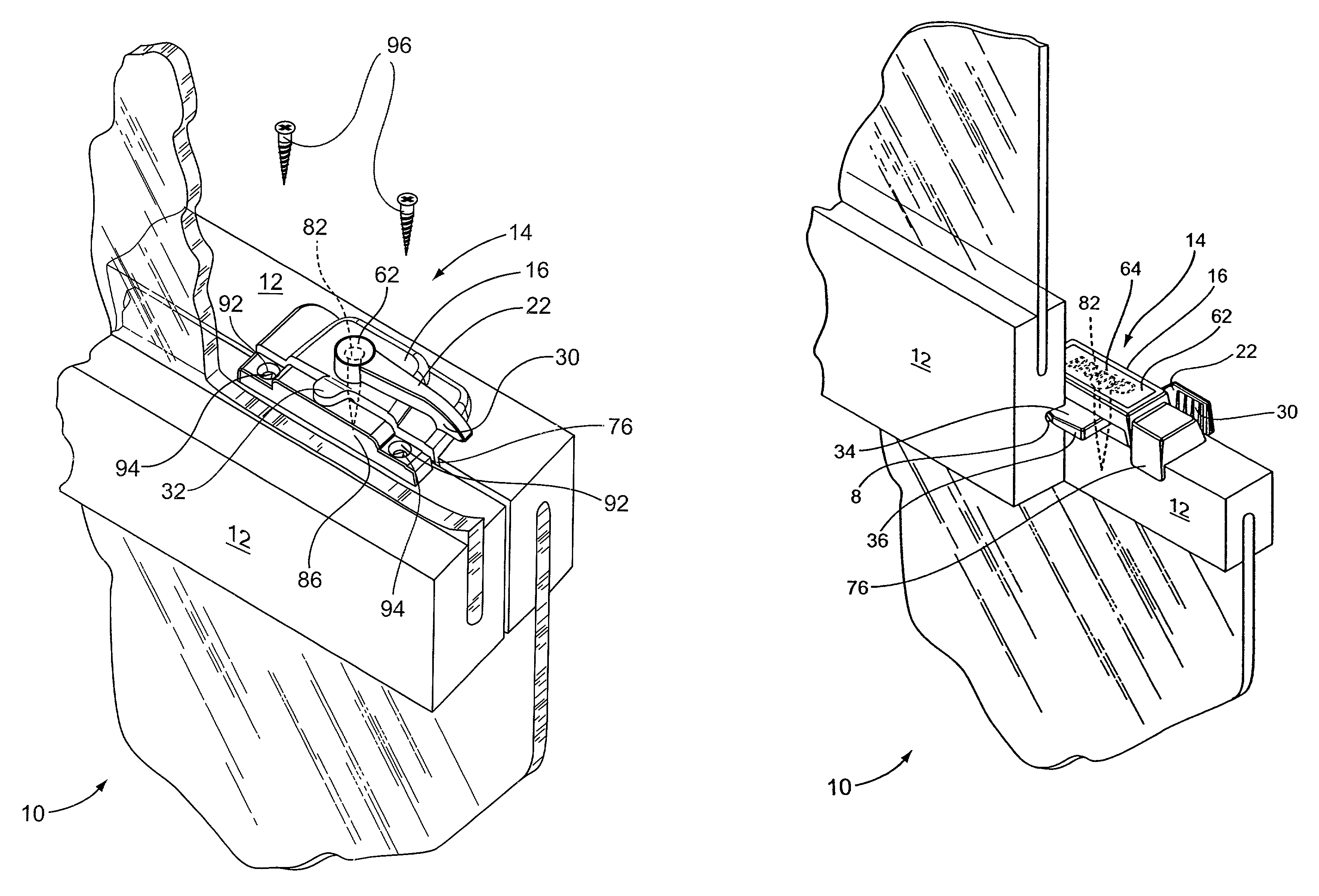
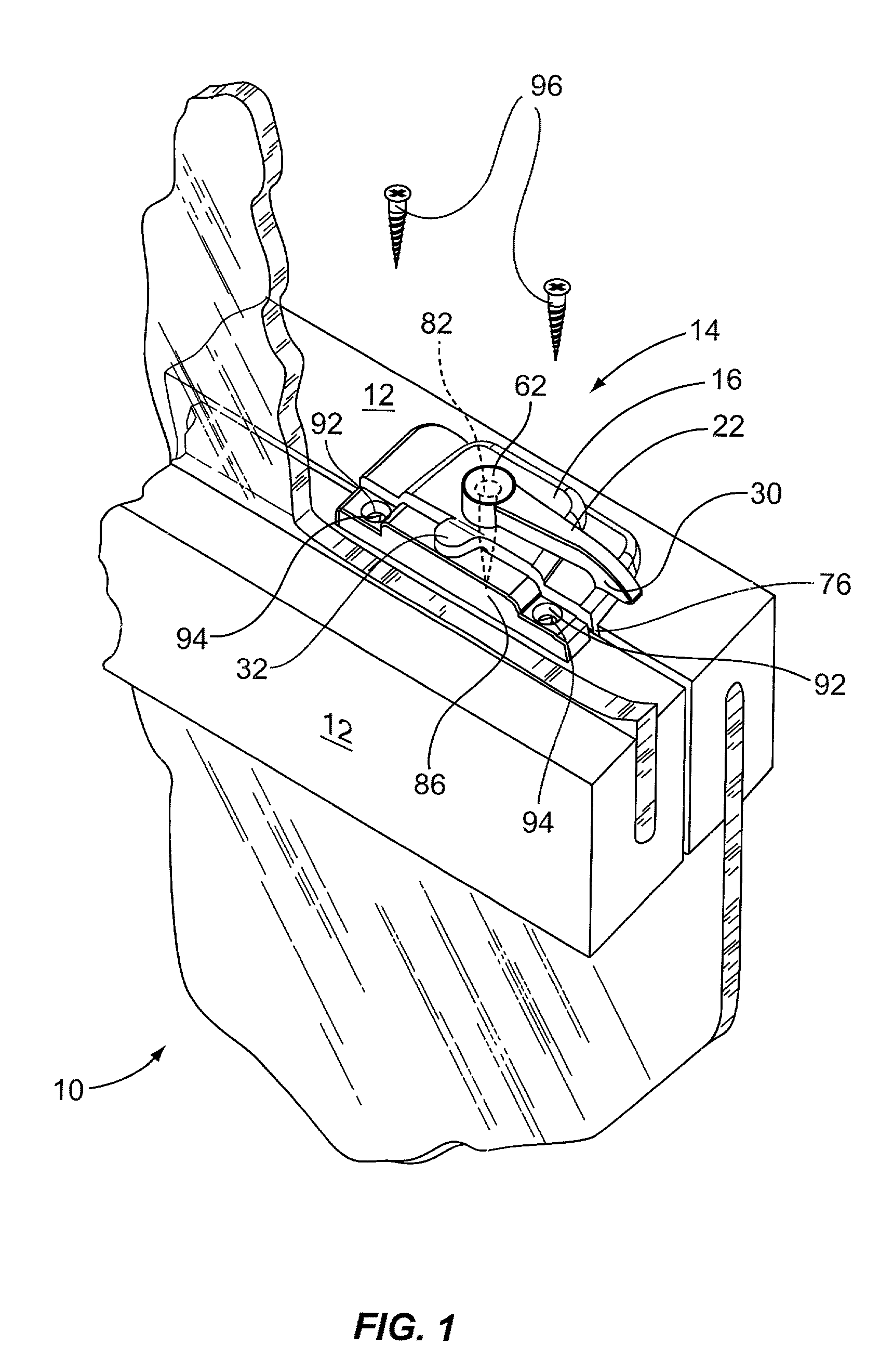
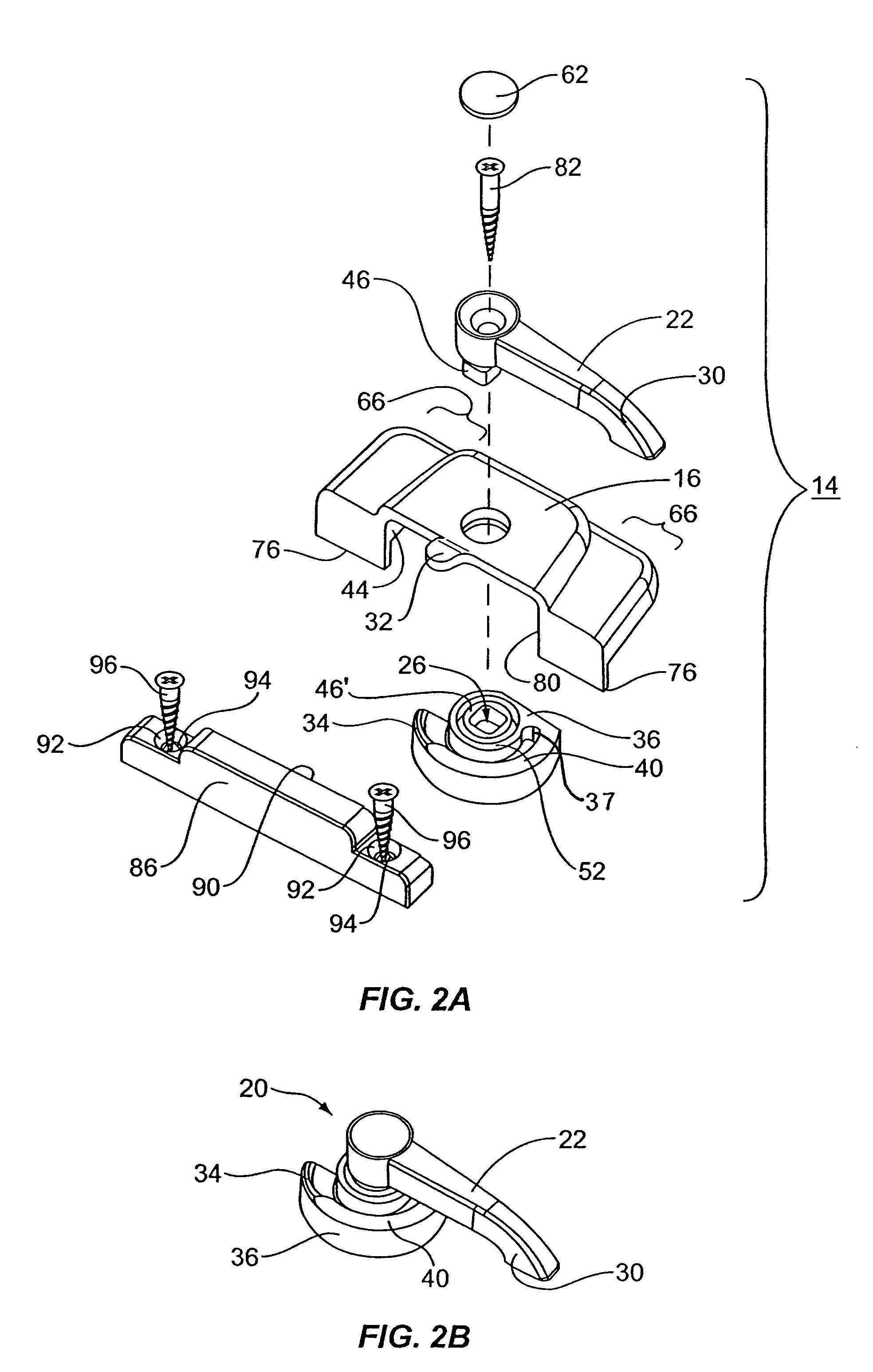
[0039]Referring now to the drawings in general and FIG. 1, FIG. 5 and FIG. 7 in particular, it will be understood that the illustrations are for the purpose of describing a preferred embodiment of the invention and an aspect of the preferred embodiment, and are not intended to limit the invention thereto. As best seen in FIG. 1, FIG. 5 and FIG. 7, a window, generally designated 10, is shown constructed according to the present invention. The window 10 includes window frame 12 and a window latch 14 fastenable to the window 10 with a distinct fastener 82. As best seen in FIG. 1, FIG. 5 and FIG. 7, any of a number of window latch designs ar...


PUM


Abstract

A locking window having a window frame and a window latch for use with the window is disclosed. The window latch, which is adapted to be attached to the window using a distinct fastener, is selectively movable between a first open position and a second locked position to secure the window sash in the closed position. The window latch includes an actuator arm, a locking arm, a non-compressible pivot and a housing. A pivot location is situated at the union of the actuator arm and the locking arm. The pivot location permits the actuator arm and the locking arm to be selectively movable between a first closed position and a second open position. The housing may include a securing feature for maintaining the housing substantially set relative to the window while at the same time permitting the actuator arm and the locking arm to be selectively movable between a first closed position and a second open position.

Description

BACKGROUND OF THE INVENTION[0001](1) Field of the Invention[0002]The present invention relates generally to a locking window and, more particularly, to a window latch for such a window.[0003](2) Description of the Prior Art[0004]Up to the end of World War II, most windows were constructed of wood. However, following the War, aluminum windows were initially constructed for low-end housing. Over time, the clear superiority of metal windows led to their use in many different types of housing. Similarly, vinyl windows were introduced in low-end housing in the beginning of the last decade. The use of vinyl windows has grown much more quickly than metal windows. In fact, the majority of windows are now constructed using vinyl.[0005]During this time, locking windows have generally used metal latches similar to those that were initially used on wooden windows. Now, although vinyl windows are the predominant construction, there has still been a hesitancy to use plastic hardware. However, met...

Claims


Application Information

Patent Timeline
Patent Type & Authority Patents(United States)
IPC IPC(8): E05C3/04
CPCE05C3/04Y10S292/47Y10T292/1041
Inventor LAWRENCE, BARRY GENE
Owner HUGHES SUPPLY OF THOMASVILLE
Why Eureka
Try Eureka