
Container for a blender

Inactive Publication Date: 2006-06-20
VITA MIX MANAGEMENT
View PDF43 Cites 65 Cited by
  • Summary
  • Abstract
  • Description
  • Claims
  • Application Information

AI Technical Summary

Benefits of technology

[0005]It is thus an object of the present invention to provide a container for a blender which assures a more complete blending of the ingredients being mixed.
[0006]It is a further object of the present invention to provide a container for a blender, as above, which creates an irregular flow pattern to discourage the formation of an air pocket around the blades in the container of the blender.
[0007]It is another object of the present invention to provide a container for a blender, as above, which will effectively mix viscous fluids without the need for manual user intervention.

Problems solved by technology

Such is an acceptable flow path when dealing with non-viscous fluids; however, when dealing with viscous fluids, such as are prevalent in frozen drinks, for example, smoothies or the like, flow problems are created.
Specifically with such fluids, recirculation a significant distance vertically above the blades is not accomplished and a fluid or ice bridge is formed above the blades.
As a result, the blades are spinning in a pocket of air and blending is thwarted.
However, with many viscous fluids, the bridge will again form requiring further user intervention.
The blending of viscous fluids without manual intervention thus remains a problem in the food processing art.

Method used


Image

  • Container for a blender
  • Container for a blender
  • Container for a blender

Examples


Embodiment Construction

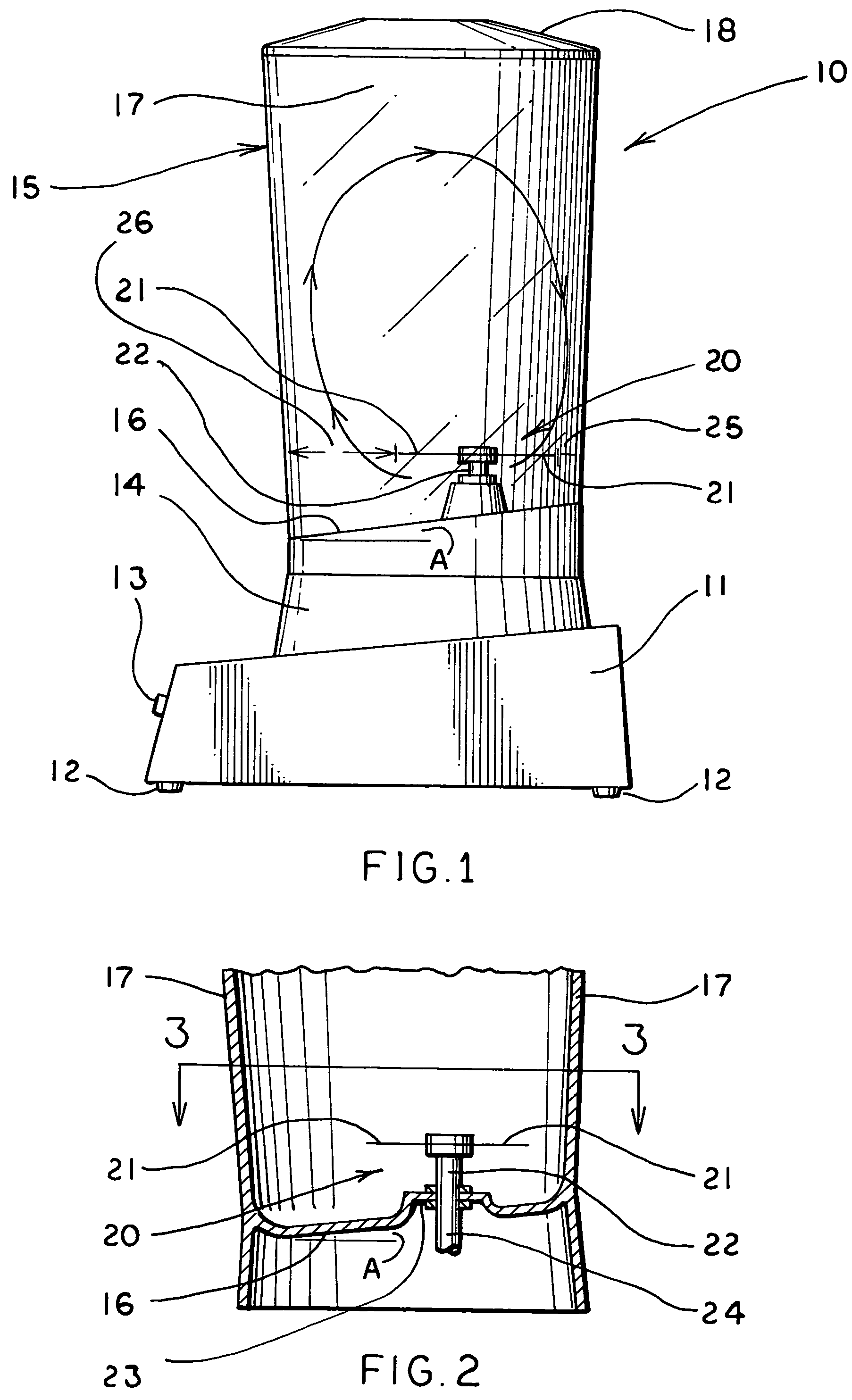
[0019]A blender is shown schematically in FIG. 1 and is indicated generally by the numeral 10. Blender 10 includes a base portion 11 which, via feet 12, may rest on any suitable operating surface. Base 11 houses a motor and other controls which may be operated at a control panel 13. A pedestal 14 is carried by base portion 11 and is adapted to receive the container made in accordance with the present invention and generally indicated by the numeral 15.

[0020]Container 15 includes a bottom surface 16 with a side wall 17 extending upwardly from the perimeter of the bottom surface 16. Side wall 17 is quite often transparent and generally defines an open top for container 15 which can be closed, as desired, by a cover or lid 18. Container 15 is most often provided with a handle (not shown) on the side wall, and usually a spout is formed at the top perimeter of the side wall so that liquid may readily be poured out of container 15.

[0021]A blade assembly, generally indicated by the numeral...


PUM


Abstract

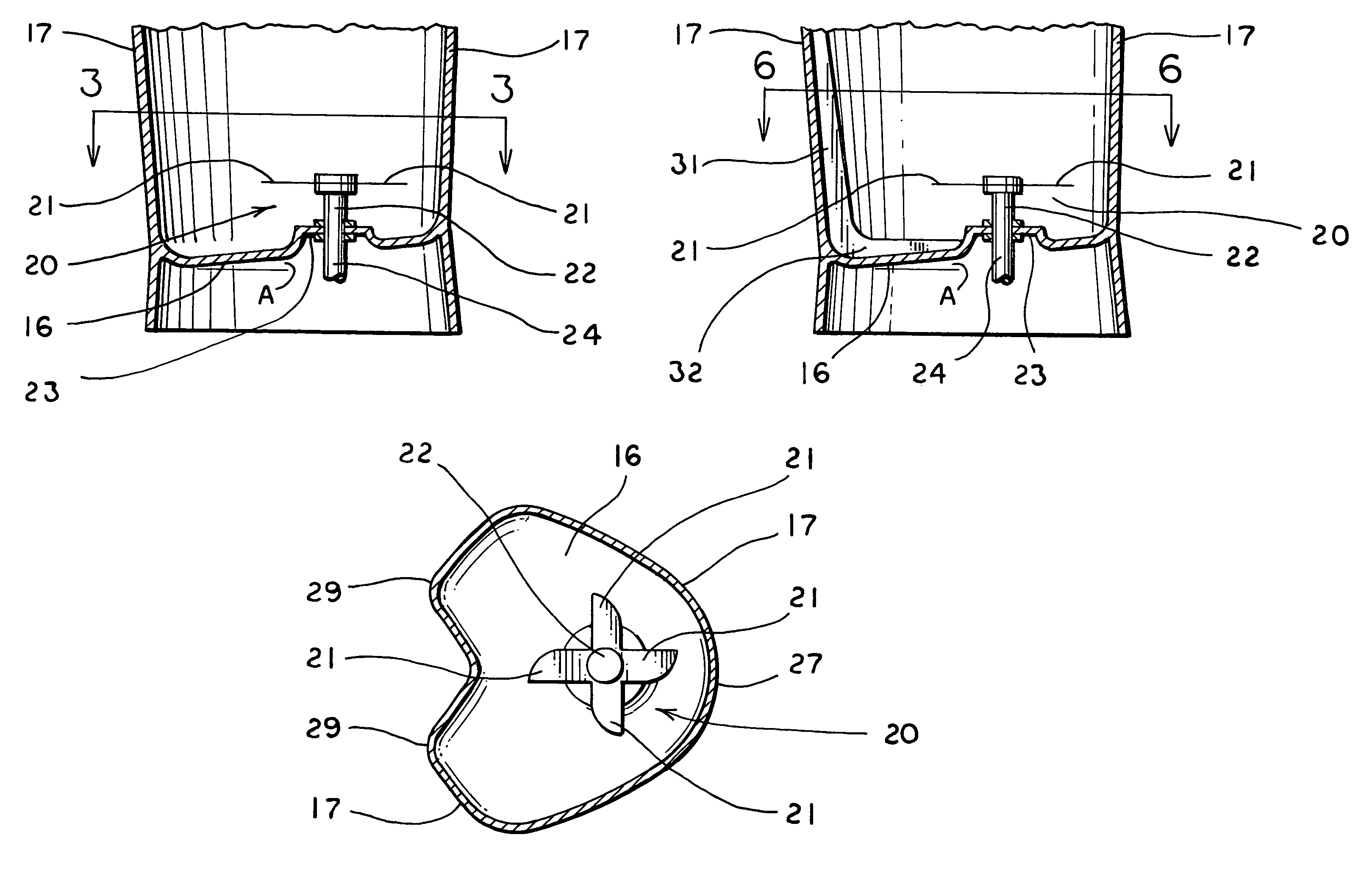
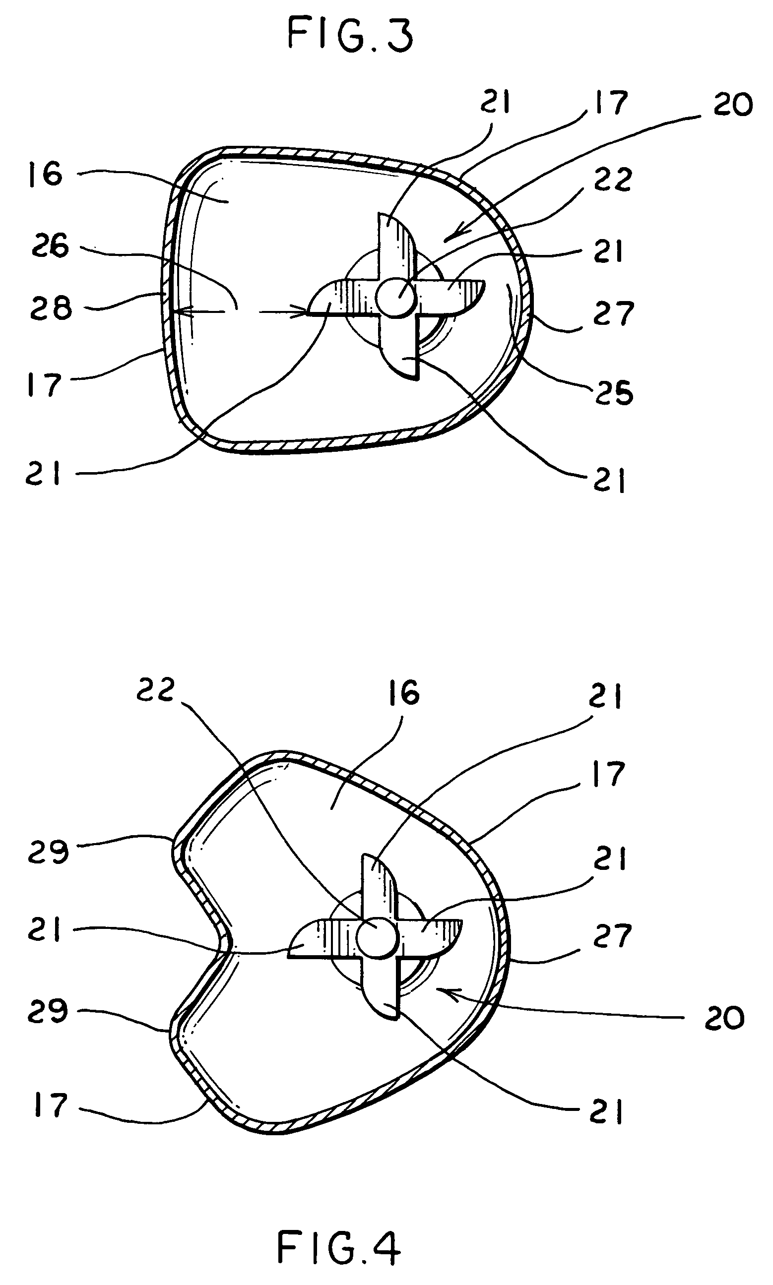
A container (15) for a blender (10) includes a bottom surface (16) having a non-symmetrically shaped perimeter. A side wall (17) extends upwardly from the perimeter of the bottom surface (16). A mixing blade assembly (20) having a plurality of blades (21) is located above the bottom surface (16) and is rotatable on an axis which is displaced from the center of the bottom surface (10). Nonuniform spaces (25, 26) are thus created between the ends of the blades (21) and the side wall (17). The bottom surface (16) is inclined at an angle relative to the plane normal to the axis of rotation of the blade assembly (20), and it, as well as the side wall (17), may be provided with a plurality of spaced vanes (31, 32).

Description

CROSS REFERENCE TO RELATED APPLICATIONS[0001]This application is based on International Patent Application No. PCT / US02 / 17827 filed on Jun. 5, 2002, which claims priority from U.S. Provisional Patent Application Ser. No. 60 / 301,081 filed Jun. 26, 2001.TECHNICAL FIELD[0002]This invention relates to a container used to blend liquids, foods and the like. More particularly, this invention relates to a blending container which is especially adapted to more efficiently blend highly viscous liquids such as encountered in the preparation of frozen drinks.BACKGROUND ART[0003]Food processors, oftentimes referred to as blenders, are employed to mix or otherwise blend or process a wide variety of foods. In a typical blender, a container is provided with a blade assembly having a plurality of blades near the bottom thereof which are rotated by a motor situated in a base or pedestal on which the container is placed. The bottom of the container is typically formed flat with a regularly-shaped peri...

Claims


Application Information

Patent Timeline
IPC IPC(8): A47J43/046A47J43/07
CPCA47J43/046A47J43/0727A47J43/0722
Inventor MILLER, BRENT A.BOOZER, RICHARD D.ANTON, MICHAEL D.
Owner VITA MIX MANAGEMENT
Learn More