Thrust bearing

a technology of thrust bearings and bearings, which is applied in the direction of bearings, shafts and bearings, rotary bearings, etc., can solve the problems of affecting the productivity of the machine, affecting the efficiency of the machine, so as to reduce the unwanted vibration of the shaft and dampen the forces placed

Inactive Publication Date: 2006-06-20
KINGSBURY INC
View PDF15 Cites 45 Cited by
  • Summary
  • Abstract
  • Description
  • Claims
  • Application Information

AI Technical Summary

Benefits of technology

[0007]It is an object of the invention to provide a thrust bearing that substantially eliminates unwanted vibration of a shaft supported by the thrust bearing while the shaft rotates during no-load operating conditions.
[0008]This object, as well as other objects, is accomplished by providing a thrust bearing, in a preferred embodiment of the invention, having a base ring, a series of shoes positioned on the base ring, and a compressible spacing member positioned between the base ring and a housing for the thrust bearing. The spacing member supports the thrust bearing when the shaft is rotati

Problems solved by technology

Vibration of shafts being supported by directed lube thrust bearings beyond acceptable limits is a great concern since such vibration is noisy, and worse, may lead to cracking of the foundations that support the machines of which the shafts are a part.
Further, such vibration may cause things, such as the thrust bearings and parts

Method used


Image

  • Thrust bearing
  • Thrust bearing
  • Thrust bearing

Examples


Embodiment Construction

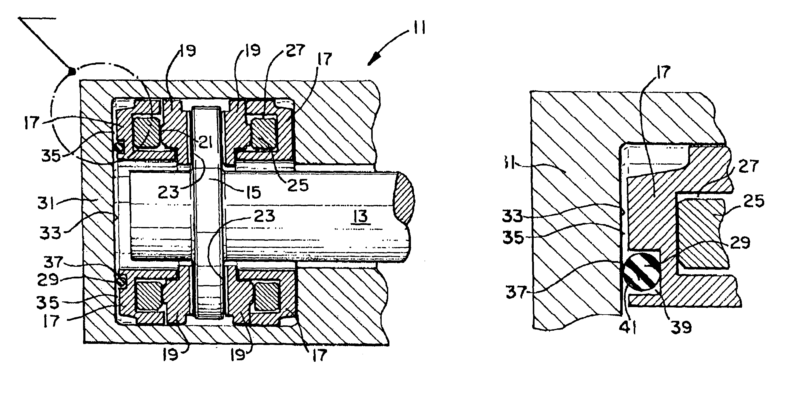
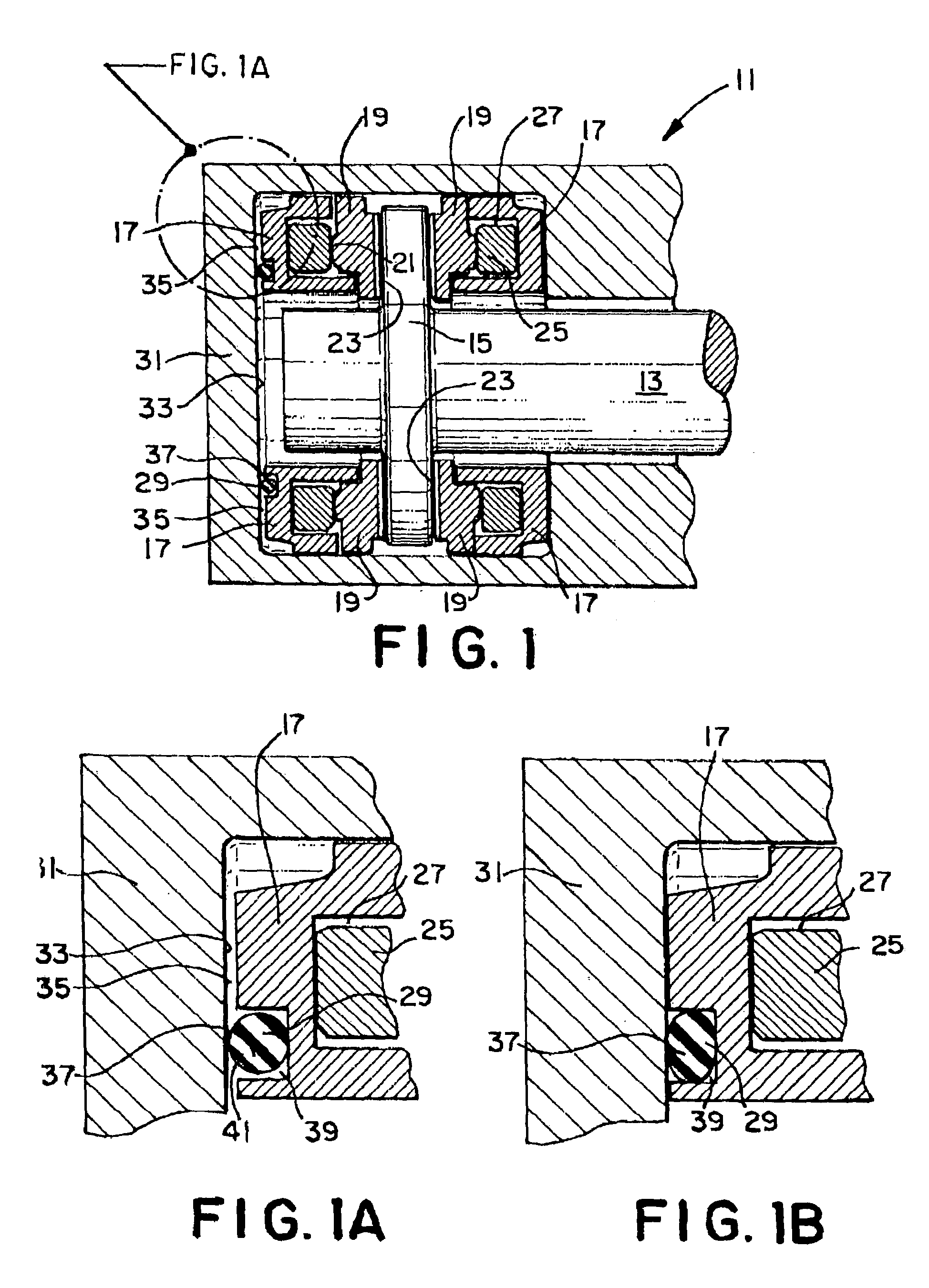
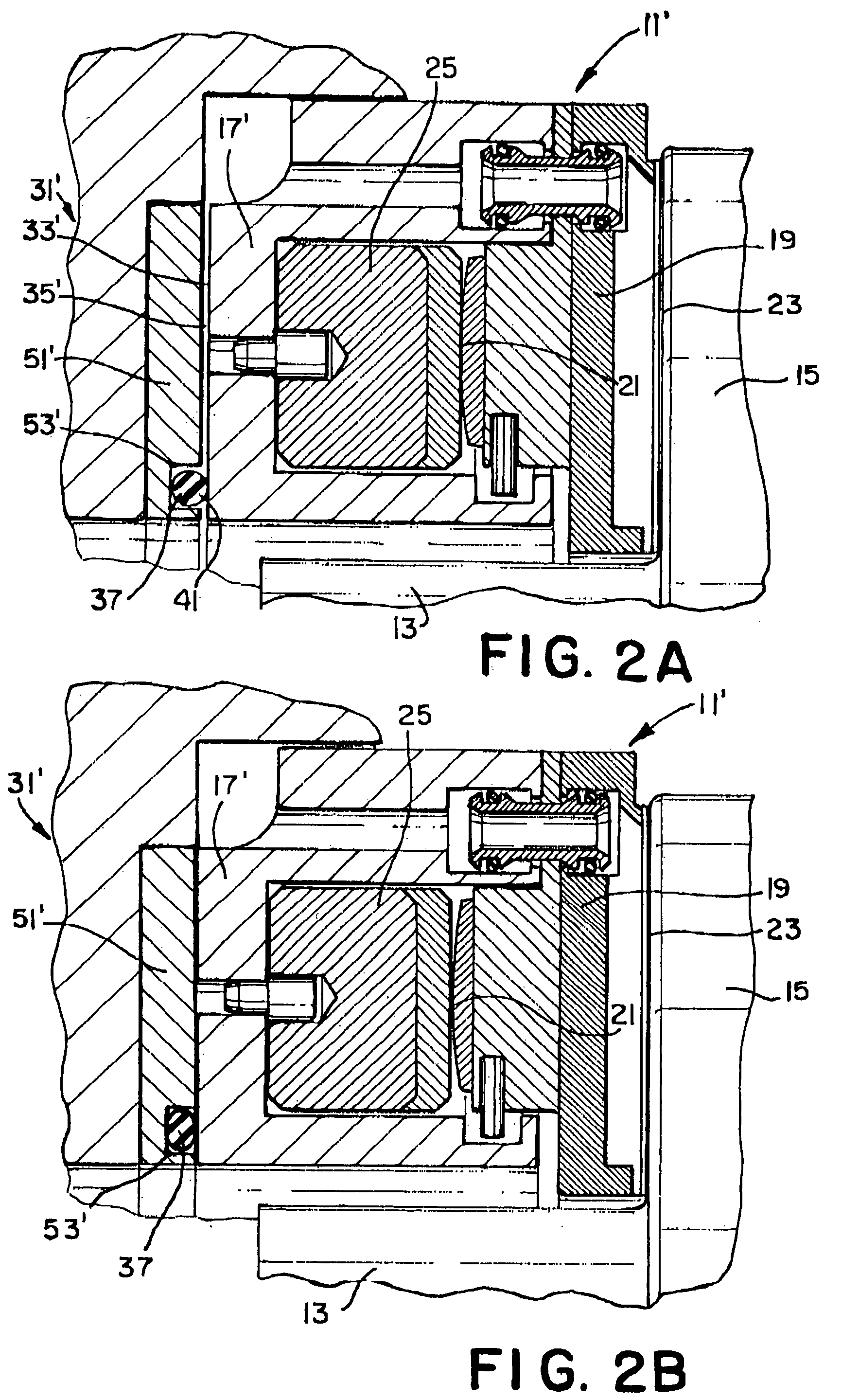
[0016]Turning now to the drawings, there is shown in FIGS. 1, 1A, and 1B a preferred embodiment of the inventive tilting pad thrust bearing 11 for use with a shaft 13 having a collar 15 mounted on shaft 13 and rotatable therewith. The thrust bearing 11 comprises a base ring 17 and a series of shoes 19 positioned around the base ring 17.

[0017]A shoe pivot 21 is mounted on each shoe 19 so as to face away from the working face 23 of the shoe 19, and is provided with a spherical surface to allow the shoe 19 to pivot freely in any direction to conform to the side surfaces of the collar 15.

[0018]Mounted between the shoes 19 and the base ring 17 in thrust bearing 11 are a series of leveling plates 25 which are placed around base ring 17 in an annular groove 27.

[0019]Shoe pivots 21 bear on the leveling plates 25.

[0020]With conventional directed lube thrust bearings, there is a certain amount of clearance between the bearing and the collar, and because of this, unwanted vibration of the shaf...


PUM


Abstract

A thrust bearing 11 for use with a shaft 13 having a collar 15 mounted the shaft 13 and rotatable therewith has a base ring 17, a series of shoes 19 positioned on the base ring 17, and a compressible resilient spacing member 29 positioned between the base ring 17 and a housing 31 for the thrust bearing 11. The spacing member 29 supports the thrust bearing 11 when the shaft 13 is rotating during no-load operating conditions, as well as dampens the forces placed on the thrust bearing 11 by the shaft 13 when the shaft 13 is rotating during no-load conditions. The spacing member 29 is sufficiently stiff that it supports the thrust bearing 11 when the shaft 13 is rotating under no-load conditions, but is sufficiently compressible to be compressed to the extent that the gap 33 between the base ring 17 and the housing 31 is eliminated due to the forces placed on the thrust bearing 11 by the shaft 13 bringing the base ring 17 into contact with the housing 31 during normal load operating conditions.

Description

BACKGROUND OF THE INVENTION[0001]1. Field of the Invention[0002]This invention relates to thrust bearings, and more particularly concerns directed lube thrust bearings.[0003]2. Description of the Prior Art[0004]Directed lube thrust bearings are now widely received in industry. One such thrust bearing is a thrust bearing designed and manufactured by Kingsbury, Inc., of Philadelphia, Pa., and marketed under the trademark LEG, which has proven to be a great advance in the design of thrust bearings since its introduction to the marketplace. The LEG thrust bearing is disclosed in Kingsbury U.S. Pat. No. 4,501,505, which is incorporated herein by reference.[0005]Vibration of shafts being supported by directed lube thrust bearings beyond acceptable limits is a great concern since such vibration is noisy, and worse, may lead to cracking of the foundations that support the machines of which the shafts are a part. Further, such vibration may cause things, such as the thrust bearings and parts...

Claims


Application Information

Patent Timeline
IPC IPC(8): F16C17/04F16C27/08F16C32/06
CPCF16C17/06
Inventor WILKES, JOSEPH J.DECAMILLO, ASCANIO M.
Owner KINGSBURY INC
Why Eureka
Try Eureka