
Spill shield for refuse collection vehicle

a technology for collecting vehicles and shells, applied in the field of shells, can solve the problems of affecting the operation of the shield or the packer ram, affecting the safety of the vehicle, and the material falling on the forward side of the shell assembly may be difficult to remove, so as to reduce the height and facilitate the fabrication and installation. the effect of cheap and easy to manufactur

Inactive Publication Date: 2006-06-20
DELAWARE CAPITAL FORMATION INC
View PDF20 Cites 12 Cited by
  • Summary
  • Abstract
  • Description
  • Claims
  • Application Information

AI Technical Summary

Benefits of technology

[0007]Among the advantages of the invention is the provision of a spill shield assembly that may be used in connection with packer face plates of various heights. Yet another advantage of the invention is the provision of a spill shield assembly that may be installed in a vehicle with minimal change in the configuration of the conventional vehicle collection compartment. Still another advantage of the invention is the provision of a spill shield assembly which is comprised of components that are relatively easy and inexpensive to fabricate and install. Another advantage of the invention is the provision of a spill shield assembly which serves, when retracted, to direct material spilled from an overhead container into the collection compartment of a vehicle. Yet another advantage of the invention is the provision of a spill shield assembly which is shorter when retracted than when extended so as to reduce the height to which a refuse container must be raised to dump its contents into the collection compartment of a vehicle. Additional advantages of this invention will become apparent from an examination of the drawings and the ensuing description.

Problems solved by technology

Furthermore, when the packer ram is being extended to push the material into the storage compartment, some of such material may tend to ride up and over the packer ram to the forward side of the face assembly.
Material that falls on the forward side of the face assembly may be difficult to remove and may interfere with the operation of the packer ram.
Any such refuse that may become lodged in either or both of the guide channels may interfere with the operation of the shield or the packer ram.

Method used


Image

  • Spill shield for refuse collection vehicle
  • Spill shield for refuse collection vehicle
  • Spill shield for refuse collection vehicle

Examples


Embodiment Construction

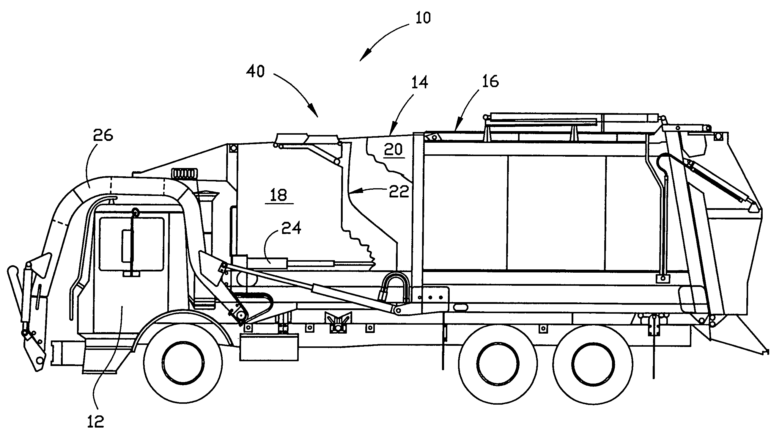
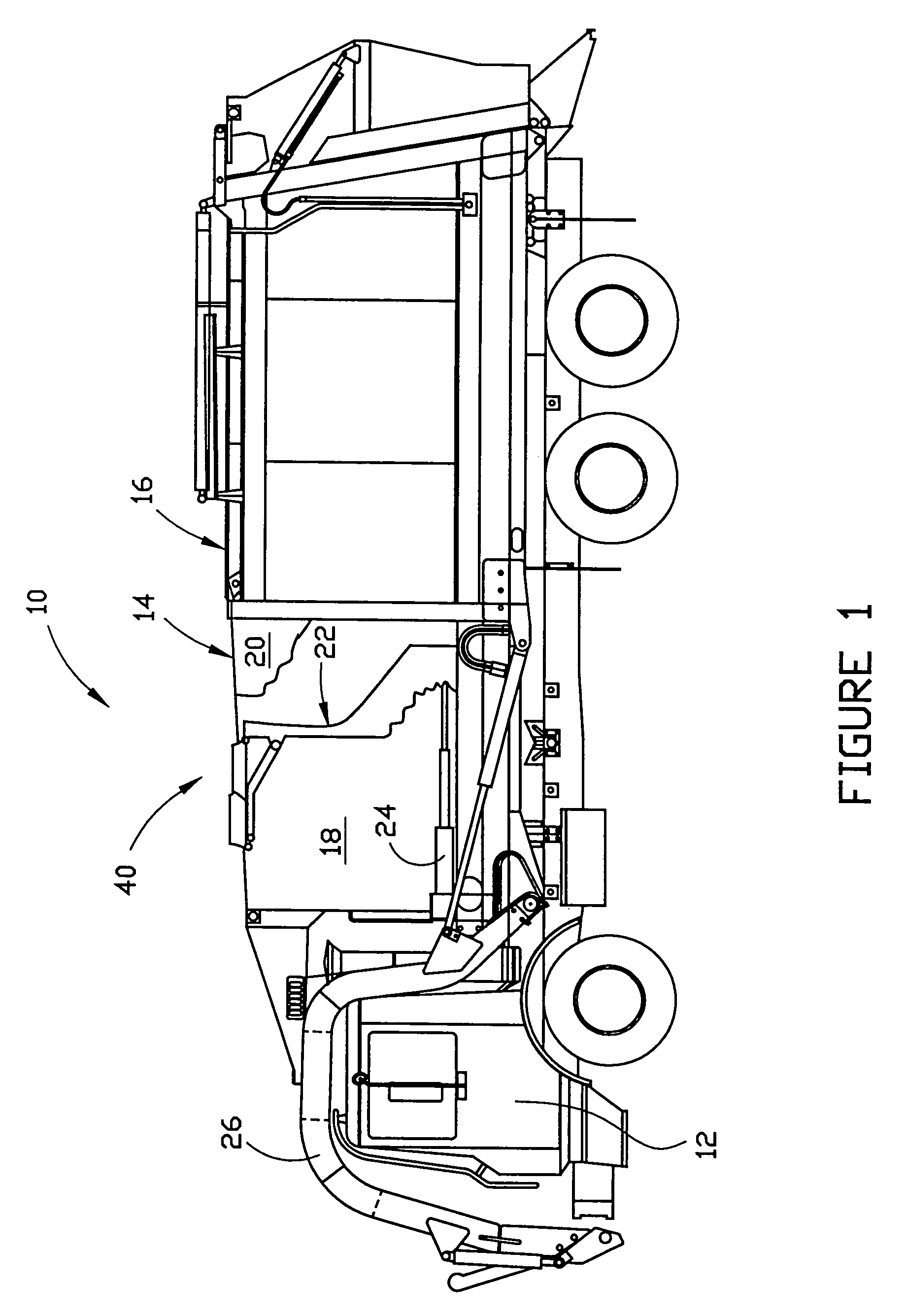
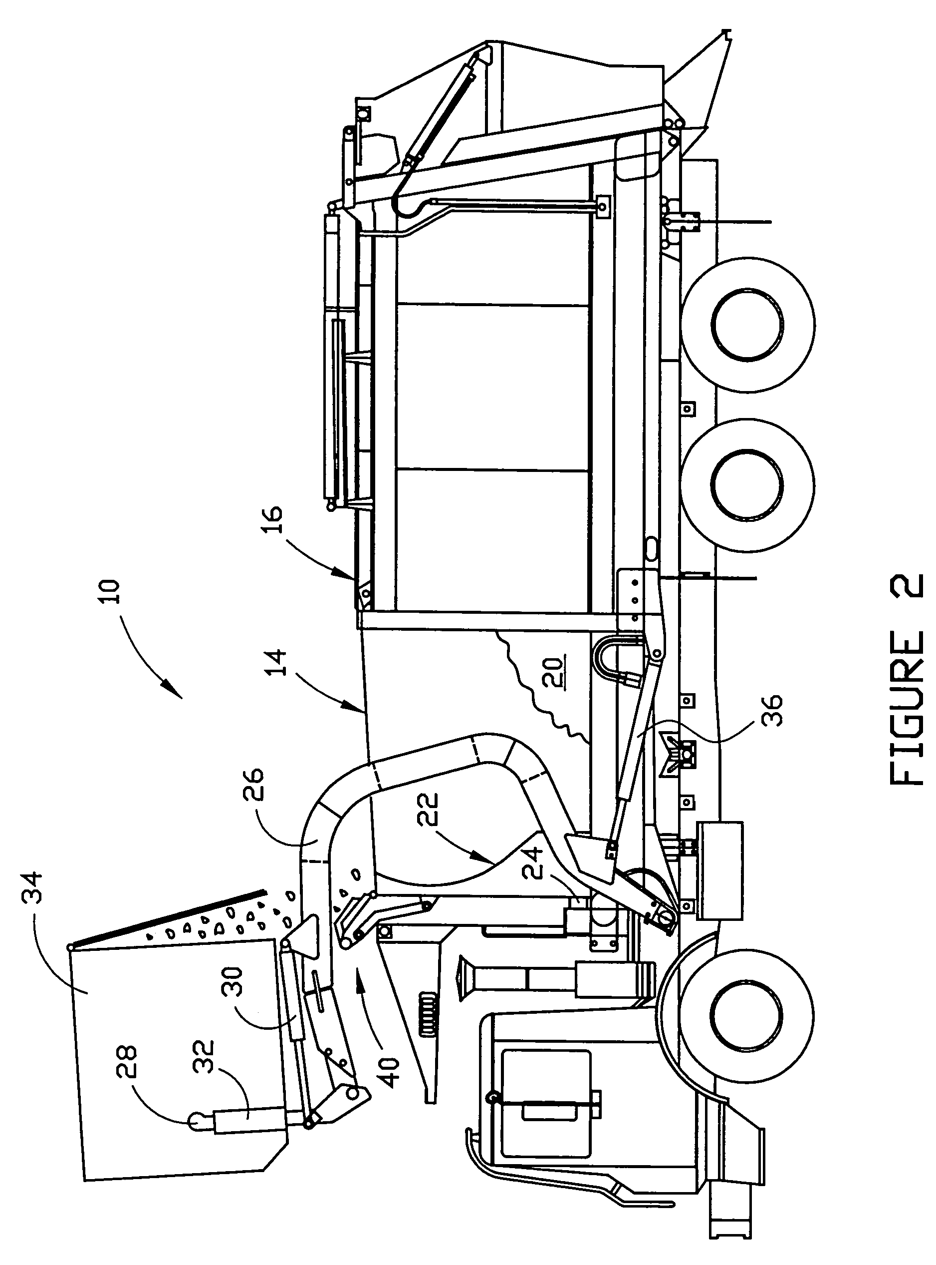
[0032]FIGS. 1, 2 and 3 illustrate a refuse collection vehicle which includes the invention. As shown therein, vehicle 10 includes cab 12, refuse collection compartment 14 and storage compartment 16. The collection compartment is provided with a retractable cover (not shown) which slides over the top of the compartment. Collection compartment 14 is defined by in part by a pair of side walls 18 and 20, although in the drawings, side wall 20 is partially cut away for clarity. The storage compartment is adjacent to the collection compartment, and in the embodiment of the vehicle illustrated in the drawings, to the rear of the collection compartment on the vehicle. The storage compartment does not typically include a retractable cover and may be defined in part by side walls that are continuations of side walls 18 and 20. The vehicle includes a packer ram assembly that is generally conventional and includes packer face plate 22 and a force-applying mechanism that is preferably comprised ...


PUM


Abstract

A spill shield assembly for a refuse collection vehicle includes a slide panel assembly comprising a front slide panel and a rear slide panel. The assembly is applicable to vehicles having a refuse collection compartment, a refuse storage compartment and a packer ram assembly having a packer face plate. One of the front and rear slide panels of the spill shield assembly is adapted to slide over the other between an extended position in which the slide panels have no more than a small amount of overlap and are disposed generally horizontally when the packer face plate is in a rearward position and a retracted position in which the slide panels are significantly overlapped and are disposed at an angle so as to direct any material falling thereon into the collection compartment when the packer face plate is in a forward position.

Description

FIELD OF THE INVENTION[0001]This invention relates generally to vehicles that include a collection compartment for receipt of refuse and a packer ram for pushing the refuse into an adjacent storage compartment and compacting it therein. The invention provides a retractable spill shield that covers a portion of the collection compartment over and in front of the packer ram as the packer ram is extended to pack the refuse and retracted to permit refuse to be deposited in the compartment.BACKGROUND AND DESCRIPTION OF THE PRIOR ART[0002]Refuse collection vehicles that are employed to collect refuse (including recyclable materials) from collection containers are well-known. Such vehicles may include a container lifting assembly which engages and lifts a container into a dumping position over a collection compartment of the vehicle. The lifting assembly may be mounted on the front of the vehicle, on the rear of the vehicle or on the side of the vehicle. As used herein, the term “front of ...

Claims


Application Information

Patent Timeline
Patent Type & Authority Patents(United States)
IPC IPC(8): B65F1/16
CPCB65F3/201B65F2003/0279
Inventor JOHNSON, GARY L.
Owner DELAWARE CAPITAL FORMATION INC
Learn More