Billiard rack laser system for positioning a rack for a billiard game

a laser system and billiard technology, applied in the field of billiards, can solve the problems of insufficient method of ensuring a repeatable rack, playing surface may tend to wear more, etc., and achieve the effect of accurate and repeatable racking of billiard balls

Inactive Publication Date: 2006-06-20
NEARHOOD STEVEN
View PDF8 Cites 26 Cited by
  • Summary
  • Abstract
  • Description
  • Claims
  • Application Information

AI Technical Summary

Benefits of technology

[0010]It is an object to provide an accurate and repeatable racking of billiard balls for a billiard game.
[0011]It is another object to provide a racking system which does not require the use of a spot mark placed on or incorporated into a playing surface of the billiard table.

Problems solved by technology

The use of the existing spot mark on the playing surface and imaginary lines has proved to be an inadequate method of assuring a repeatable rack.
This is an undesirable result, particularly in competitive tournaments.
By providing a conventional spot mark on the table surface, the playing surface may tend to wear more at one end of the playing surface where the rack is always positioned.

Method used


Image

  • Billiard rack laser system for positioning a rack for a billiard game
  • Billiard rack laser system for positioning a rack for a billiard game
  • Billiard rack laser system for positioning a rack for a billiard game

Examples


embodiment 100

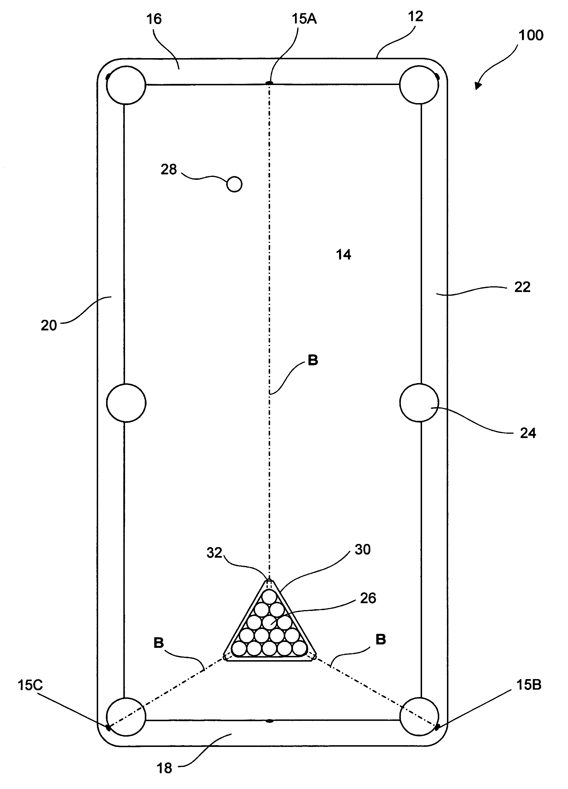
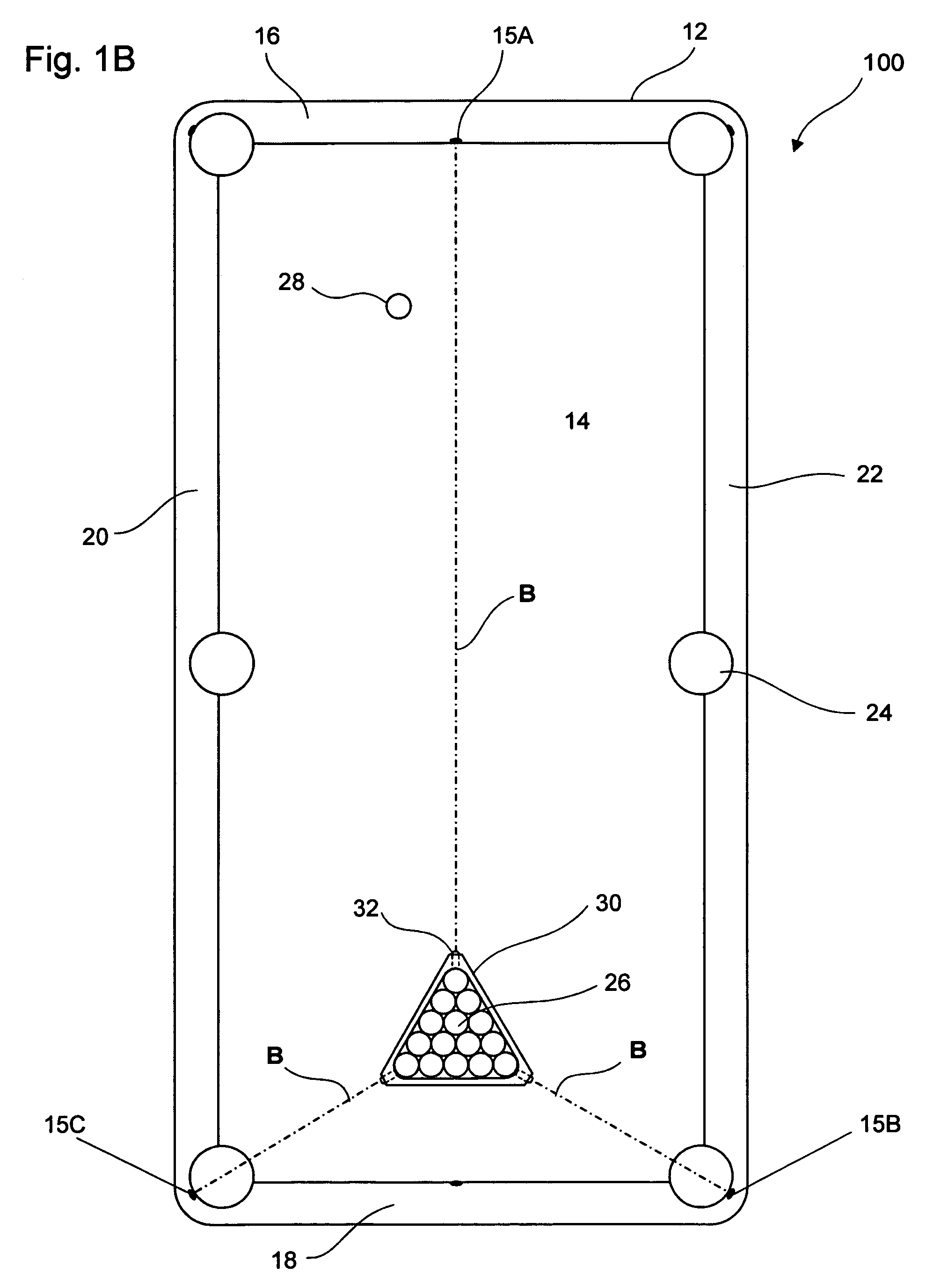
[0031]FIGS. 1B and 2B illustrates another embodiment 100 wherein, multiple lasers 32 can be incorporated into ends 34A, 34B and 34C. In this instance, alignment markings 15A, 15B and 15C can be provided on the table 12 as shown, for example, to effect a proper alignment.

embodiment 200

[0032]Still another embodiment 200 seen in FIGS. 1C and 2C can include a beam splitter 202 which provides for a plurality of beams B and B′ to be used on marks 215 to perfect alignment. In this instance, part of the beams B′ can be used to define a cue line C such that the cue ball may be placed for starting the game.

[0033]The laser 32 can include circuits and lenses known to the art and can be incorporated into a housing 37 which is configured to fit within the bored surface 35. It is understood that the laser 32 includes a power source, such as battery, operably disposed within the housing 37. It is understood that while certain forms of the present invention have been illustrated and described herein, it is not to be limited to the specific forms or arrangements of parts described and shown.

[0034]FIG. 6 illustrates another embodiment 300 of the invention, wherein a laser 32′ is disposed within a housing 50 which can be provided on one side 22, for example, of the table 12. The la...


PUM


Abstract

A billiard rack laser system for positioning a rack for a billiard game includes a pool table having an alignment mark and a pool rack having a laser operably connected thereto such that when the rack is placed on the table, the laser is equipped to illuminate a beam which when directed at the alignment mark illuminates the same thereby indicates a proper spot of the rack for positioning the same on the table.

Description

BACKGROUND OF THE INVENTION[0001]1. Field of the Invention[0002]The present invention relates to the billiards. More particularly, the invention relates to an improvement in spotting a rack for billiards.[0003]2. Related Art[0004]Billiards requires the use of a table, set of billiard balls, cue ball, cue sticks, rack and bridge. Due to the competitive nature of the game of billiards, it is desired to have a repeatable and precise location of an initial rack. This precludes an unfair advantage for a player.[0005]There is a need for providing a repeatable and precise initial rack for a billiard game. A typical billiard table includes a spot mark physically placed on the top surface of the playing table to identify the location of the placement of an initial rack. This mark is intended to coincide with the location of a lead ball inside the rack with the other playing balls disposed behind the lead ball within the rack.[0006]The lead ball is placed on top of this spot mark and a remain...

Claims


Application Information

Patent Timeline
Patent Type & Authority Patents(United States)
IPC IPC(8): A63D15/00
CPCA63D15/005
Inventor NEARHOOD, STEVEN
Owner NEARHOOD STEVEN
Why Eureka
Try Eureka