
Solid-state synchro/resolver converter

a converter and solid-state technology, applied in the field of solid-state synchro/resolver converter, can solve the problems of increasing the difficulty and cost of maintaining these older sensors, prohibitively expensive methods, prohibitively expensive, etc., and achieve the effect of simple and inexpensive conversion

Inactive Publication Date: 2006-06-20
HONEYWELL INT INC
View PDF6 Cites 3 Cited by
  • Summary
  • Abstract
  • Description
  • Claims
  • Application Information

AI Technical Summary

Benefits of technology

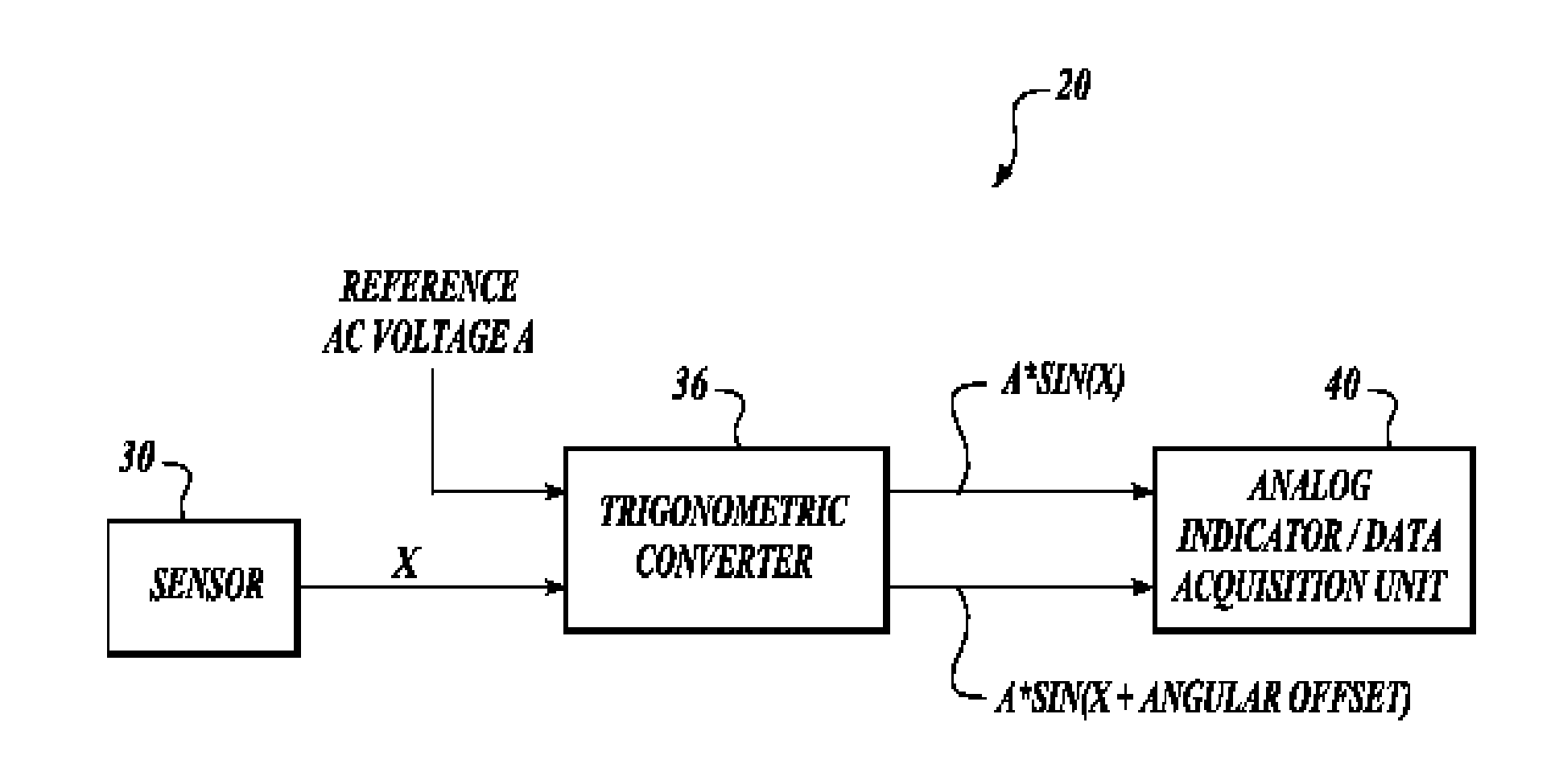
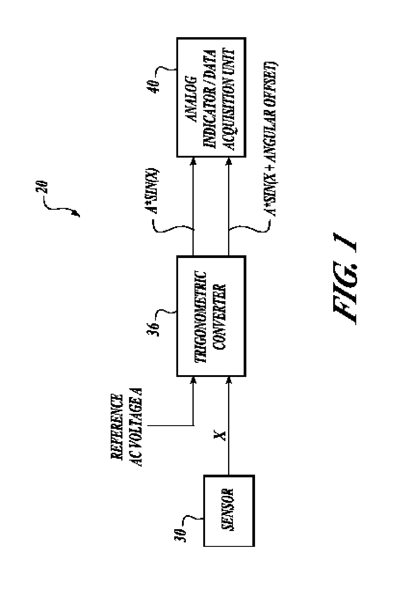
[0005]The present invention provides methods and systems for simply and inexpensively converting the signals of solid-state sensors for use by analog systems and indicators. An embodiment of the system receives a DC voltage value from at least one sensor, converts the DC voltage value into one or more analog signals based on a reference AC voltage signal, and performs at least one of outputting or storing the generated analog signals. The trigonometric conversion is performed either digitally then converted to analog, or is performed using an analog trigonometric converter.

Problems solved by technology

Because older aircraft have analog sensors, it is becoming increasingly difficult and costly to maintain these older sensors.
The problem with replacing the old style sensors with new solid-state sensors is that the existing systems that connect with the old style sensors still need to receive the data in the same format that was outputted by the old style sensors.
This, of course, is prohibitively expensive.
However, these methods are costly and difficult to implement.
Traditional methods require memory (for look-up tables) and / or oscillators that lower system reliability and utilize sync signals which can be susceptible to EMI.

Method used


Image

  • Solid-state synchro/resolver converter
  • Solid-state synchro/resolver converter
  • Solid-state synchro/resolver converter

Examples


first embodiment

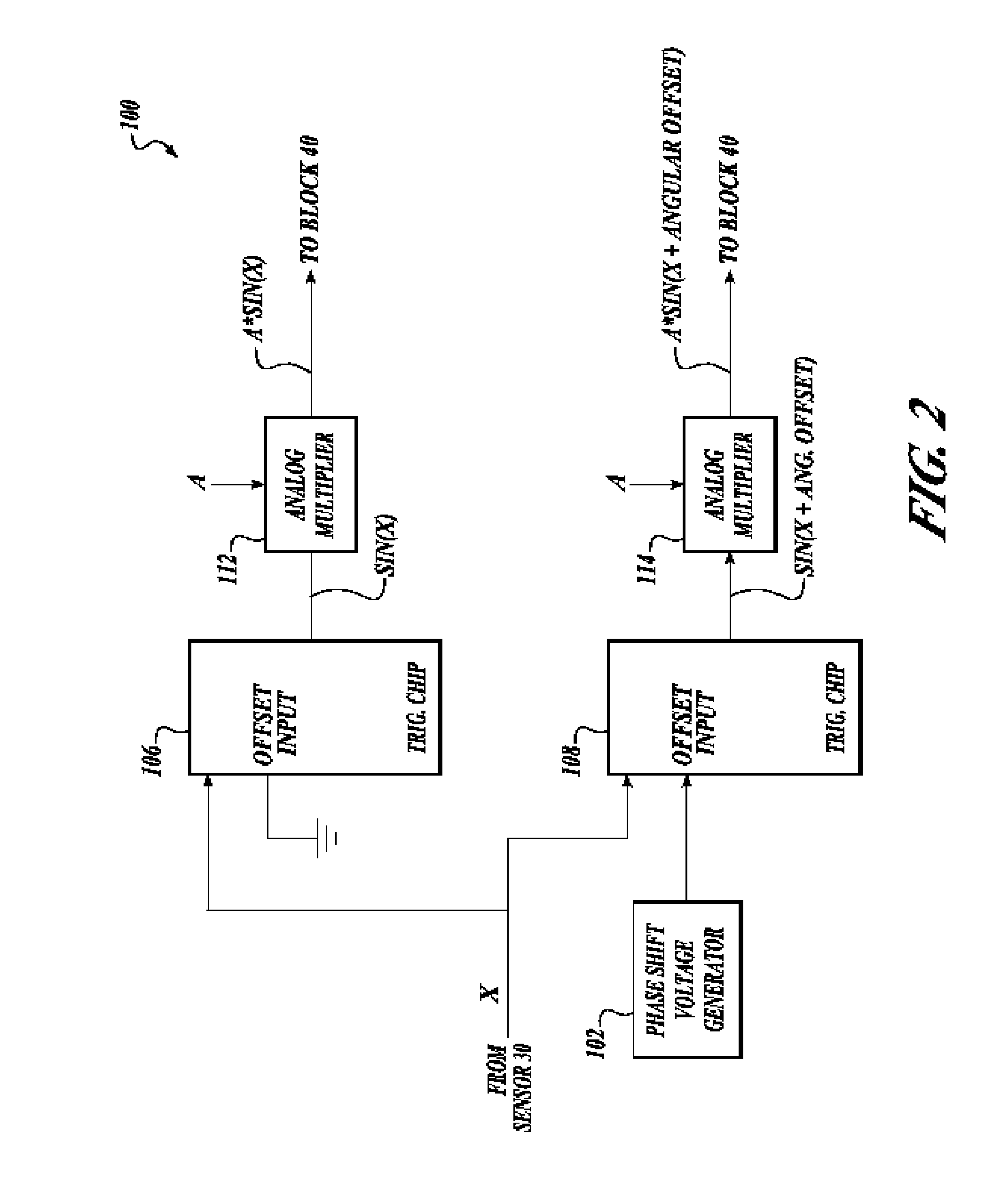
[0011]FIG. 2 illustrates a converter 100 that provides the functions of the trigonometric converter 36 shown in FIG. 1 in accordance with a The converter 100 includes a phase shift voltage generator 102, first and second trigonometric chips 106 and 108, and first and second analog multipliers 112 and 114.

[0012]In one embodiment, the first and second trigonometric chips 106 and 108 are off-the-shelf trigonometric processing chips, such as the AD639 produced by Analog Devices™. More than two trigonometric chips can be included depending on the desired output or a single chip may be configured to include multiple inputs and outputs for producing desired outputs. The analog multipliers 112 and 114 may also be off-the-shelf devices. In one embodiment, the phase shift voltage generator 102 includes a voltage divider, but could be any of a number of different off-the-shelf voltage generators.

[0013]The first and second trigonometric chips 106 and 108 receive the DC voltage value X produced...

second embodiment

[0014]FIG. 3 illustrates a converter 140 that provides the functions of the trigonometric converter 36 shown in FIG. 1 in accordance with a The converter 140 includes an analog to digital (A / D) converter 148, a non-linear transfer function component 150, a digital offset component 152, and first and second multiplying digital to analog (D / A) converters 156 and 158. The components 150 and 152 may be implemented as a field programmable gate array (FPGA) or other functionally comparable device. The A / D converter 148 receives the DC voltage value X from the sensor 30 and converts it into a digital value. The non-linear transfer function component 150 receives the digital output of the A / D converter 148 and converts that linear signal to output a digital representation of a trigonometric signal to the first D / A multiplier 156 and the digital offset component 152. Equation No. 1 is an example of a non-linear transfer function that is utilized by the component 150 to generate the digital ...


PUM


Abstract

Methods and systems for simply and inexpensive converting the signals of solid-state sensors for use by analog systems and indicators. An embodiment of the system receives a DC voltage value from at least one sensor, converts the DC voltage value into one or more analog signals based on a reference AC voltage signal, and performs at least one of outputting or storing the generated analog signals. The conversion is performed digitally then converted to analog or is performed using an analog trigonometric converter.

Description

BACKGROUND OF THE INVENTION[0001]Aircraft sensors and associated recording units or cockpit indicators are typically either communicating all digital or analog information. Newer aircraft have solid-state sensor technology with processing systems and indicators that are designed to operate on the output of the solid-state sensors. Because older aircraft have analog sensors, it is becoming increasingly difficult and costly to maintain these older sensors. Thus, it is preferred to replace old sensors with newer, cheaper, and easier to maintain solid-state sensors, such as Micro Electro Mechanical Systems (MEMS) sensors.[0002]The problem with replacing the old style sensors with new solid-state sensors is that the existing systems that connect with the old style sensors still need to receive the data in the same format that was outputted by the old style sensors. One solution is to replace the processing systems and indicators with processing systems and indicators that are compatible ...

Claims


Application Information

Patent Timeline
IPC IPC(8): H03M1/48
CPCG06G7/22H03M1/645G06J1/00
Inventor KOSHT, DANIAL L.TERPSTRA, LARRY J.
Owner HONEYWELL INT INC
Learn More