Finger movement detection method and apparatus

a finger movement and finger technology, applied in the field of finger movement detection methods and apparatuses, can solve the problems of such a small size of the finger movement detection method and the method of detecting the finger movement on the sensor face, and have not yet been proposed

Active Publication Date: 2006-06-20
CYPRESS SEMICON CORP
View PDF12 Cites 84 Cited by
  • Summary
  • Abstract
  • Description
  • Claims
  • Application Information

AI Technical Summary

Problems solved by technology

The track pad, however, requires a sensor face larger than a fingertip for detecting the position of the fingertip, and hence it is not preferable for small portable equipment, such as a mobile phone.
However, any method of detecting a finger movement from a fingerprint image and any configuration of a pointing device realized by the method have not yet been proposed specifically.
However, any method and apparatus for detecting the finger movement on the sensor face having such a small size have not yet been proposed.

Method used


Image

  • Finger movement detection method and apparatus
  • Finger movement detection method and apparatus
  • Finger movement detection method and apparatus

Examples


Embodiment Construction

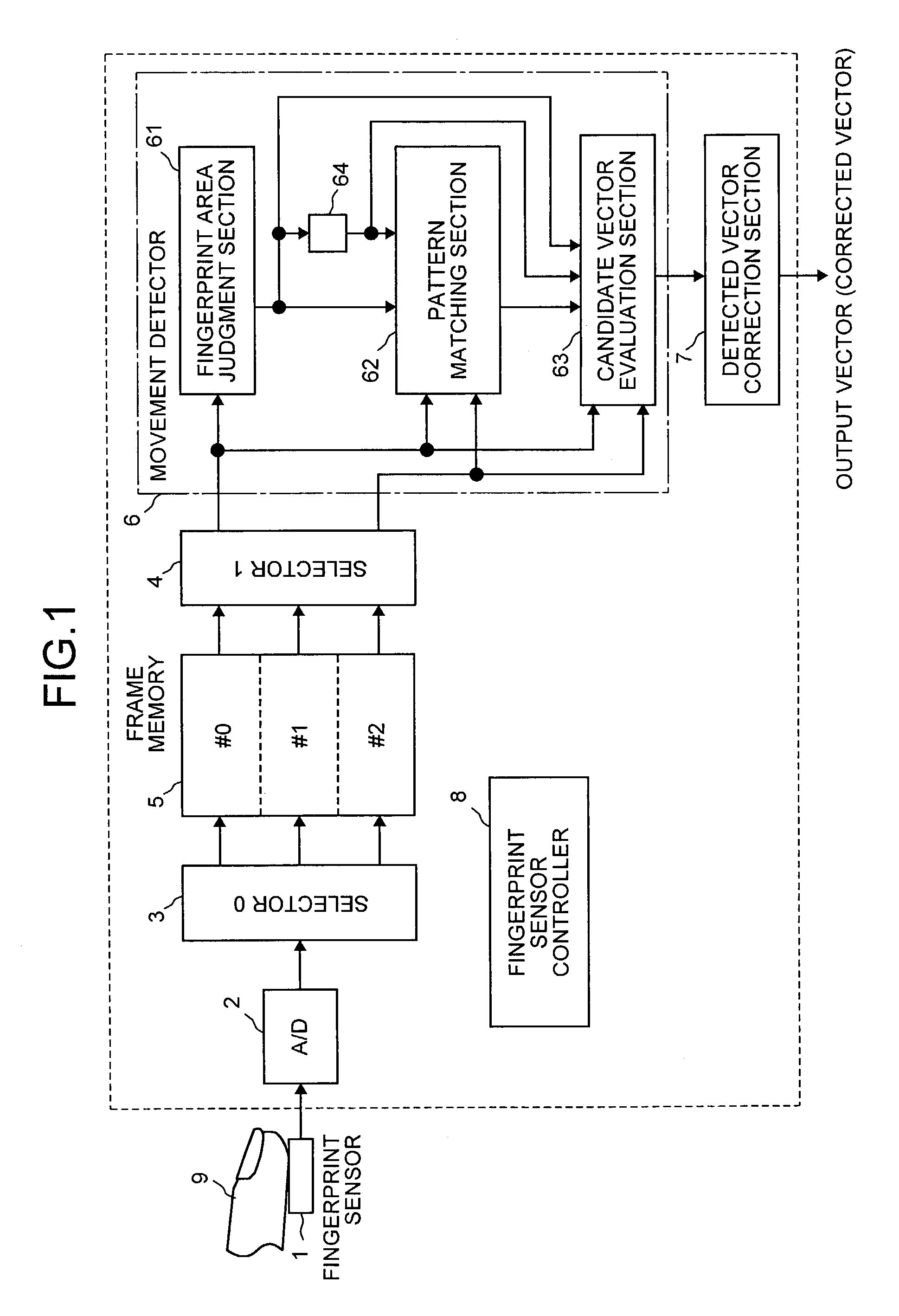
[0021]An embodiment of the present invention will be explained in detail below with reference to the drawings. FIG. 1 is a block diagram functionally showing the configuration of the finger movement detection apparatus according to the embodiment of the present invention. As shown in FIG. 1, this detection apparatus comprises an electronic fingerprint sensor 1, an A / D converter 2, two selectors 3 and 4, a frame memory 5, a movement detector 6, a detected vector correction section 7, and a fingerprint sensor controller 8 that controls overall operation timing.

[0022]The fingerprint sensor 1 is smaller than a fingertip 9, and detects a fingerprint in an area smaller than the fingertip 9. The A / D converter 2 converts sensor image data consisting of an analog signal captured by the fingerprint sensor 1 into data consisting of a digital signal. The frame memory 5 has three banks, for example, #0, #1 and #2, though not particularly limited. Of the three banks, one bank is used for writing,...


PUM


Abstract

A fingerprint area and a barycentric position of the area are obtained for a current sensor image, and an area near the barycentric position is divided into a plurality of small blocks. An image area that agrees with a fingerprint image is searched for, for each of the small blocks with respect to the fingerprint area in a previous sensor image. A candidate vector is obtained from a deviation between the position of the small block in the current sensor image and the position of the image area in the previous sensor image corresponding to the small block. A candidate vector with the highest matching degree between the fingerprint images in the current and previous sensor images is selected from the candidate vectors to obtain a detected vector, and the detected vector is corrected to exclude an influence of erroneous detection and to control a movement of a pointer.

Description

CROSS-REFERENCE TO RELATED APPLICATIONS[0001]This application is based upon and claims the benefit of priority from the prior Japanese Patent Application No. 2002-089517, filed on Mar. 27, 2002, the entire contents of which are incorporated herein by reference.BACKGROUND OF THE INVENTION[0002]1) Field of the Invention[0003]The present invention relates to a method and apparatus for detecting a movement of a finger by performing pattern matching between a past fingerprint image and a current fingerprint image. More specifically, the present invention relates to a finger movement method and apparatus suitable to be applied to a pointing device for small portable equipment using a fingerprint image.[0004]2) Description of the Related Art[0005]Conventionally, an electronic track pad equipped in a notebook-sized personal computer has been known as a pointing device. The track pad, however, requires a sensor face larger than a fingertip for detecting the position of the fingertip, and hen...

Claims


Application Information

Patent Timeline
Patent Type & Authority Patents(United States)
IPC IPC(8): G09G5/08G01B7/28A61B5/11A61B5/117G01B11/00G01B11/24G06F3/033G06F3/0346G06F3/041G06K9/00G06T1/00
CPCG06K9/00026G06F3/03547G06V40/1335
Inventor NISHIKAWA, SHOU
Owner CYPRESS SEMICON CORP
Why Eureka
Try Eureka