Tool and a method for assessing an indicator mark position

a technology of indicator marks and tools, applied in the direction of instruments, transportation and packaging, vehicle arrangements, etc., can solve the problem of difficult accurate assessment of the position of indicator marks, and achieve the effect of quick and easy assessmen

Active Publication Date: 2006-06-27
FORD GLOBAL TECH LLC
View PDF12 Cites 0 Cited by
  • Summary
  • Abstract
  • Description
  • Claims
  • Application Information

AI Technical Summary

Benefits of technology

[0007]According to one aspect of the present invention, a tool for assessing the position of an indicator mark disposed on a seat of a vehicle is provided. The tool includes an arm and a plurality of line generating lasers. The arm is adapted to contact an anchorage disposed proximate the seat. The plurality of line generating lasers are associated with the arm and are adapted to project a set of beams toward the seat. The set of beams define an area indicative of a desired location of the indicator mark. The set of beams permit the position of the indicator mark to be quickly and easily assessed without altering the location or orientation of the indicator mark.
[0011]The tool may include a mounting assembly connected to the arm and adapted to receive the plurality of line generating lasers. The mounting assembly may include an adjustment feature to adjust the position of a line generating laser. The mounting assembly may include a handle portion. The handle portion improves tool ergonomics when grasping and positioning the tool.

Problems solved by technology

Accurately assessing the location of an indicator mark is difficult not only due to tolerance variations, but also due to the complex surface geometries and contours of interior vehicle surfaces.

Method used


Image

  • Tool and a method for assessing an indicator mark position
  • Tool and a method for assessing an indicator mark position
  • Tool and a method for assessing an indicator mark position

Examples


Embodiment Construction

)

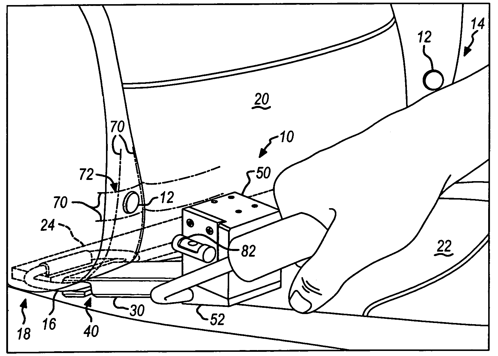
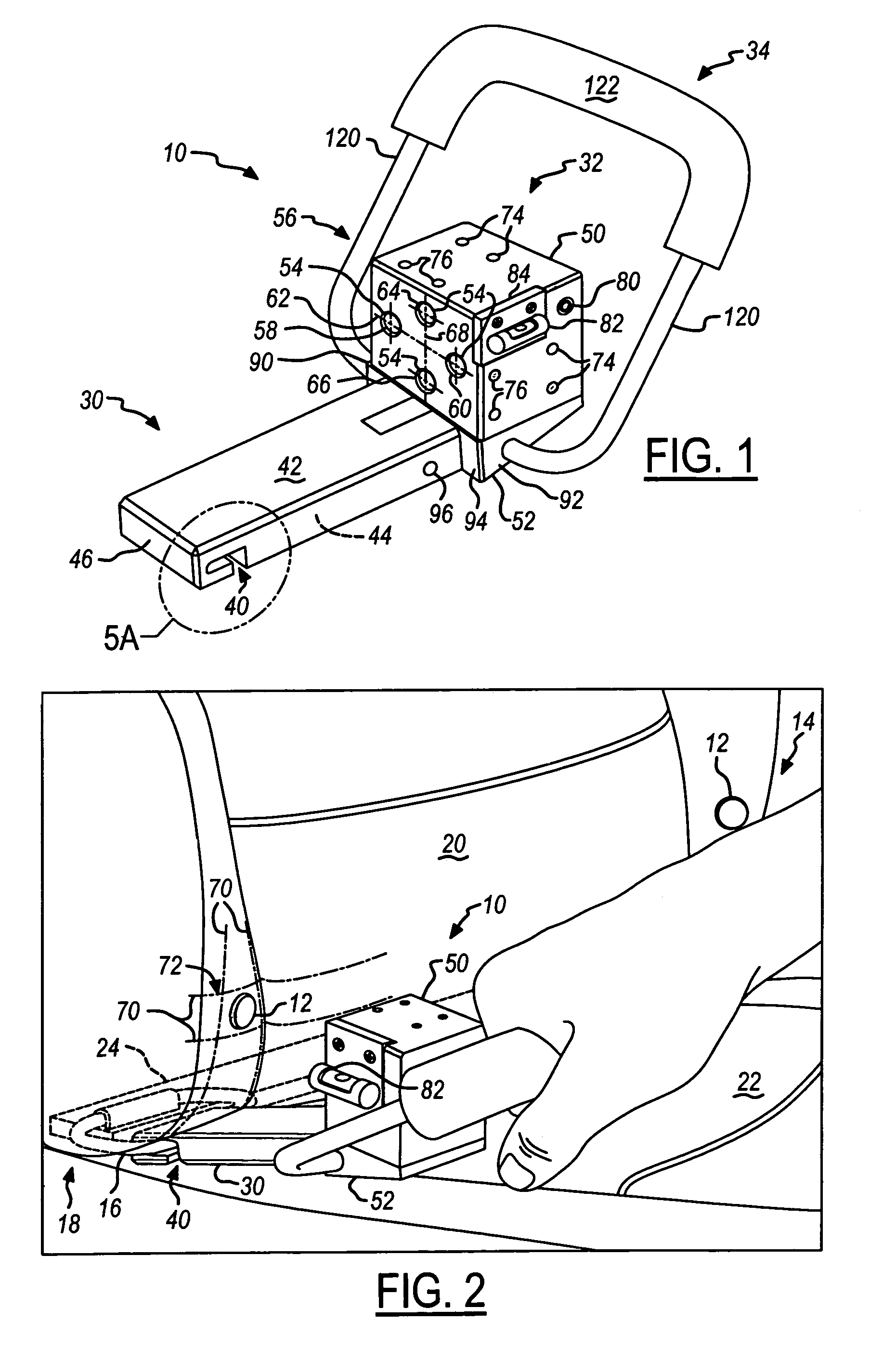
[0026]Referring to FIGS. 1 and 2, a tool 10 for assessing a position of an indicator mark 12 disposed on a vehicle seat 14 is provided. The indicator mark 12 conspicuously identifies the approximate location of an anchorage 16 of a child restraint anchorage system 18. The indicator mark 12 may be of any suitable type and may include one or more words, symbols, or pictograms. For example, the indicator mark 12 may be configured as a button disposed on a seat back 20 or seat bottom 22 of the vehicle seat 14.

[0027]The anchorage 16 is adapted to receive a component of a child restraint system, such as a mating feature of a child safety seat or a tether strap. The anchorage 16 is adapted to transmit force from the child restraint system to the vehicle. In the embodiment shown, the anchorage 16 is coupled to a bracket 24 that is disposed on a portion of the vehicle. Alternatively, the bracket 24 may be omitted and the anchorage 14 may be attached to another vehicle component, such as a v...


PUM


Abstract

A tool for assessing the position of an indicator mark disposed on a seat of a vehicle. The tool includes an arm adapted to contact an anchorage and a plurality of lasers adapted to project a set of beams toward the seat. The set of beams define an area indicative of a desired location of the indicator mark.

Description

BACKGROUND OF THE INVENTION[0001]1. Field of the Invention[0002]The present invention relates to a tool and a method for assessing a position of an indicator mark disposed on a vehicle surface, and more particularly to a tool and a method for assessing the position of a child restraint anchorage indicator mark disposed on a seat of a vehicle.[0003]2. Background Art[0004]Motor vehicles may include a child restraint anchorage system. A child restraint anchorage system uses a plurality of anchorages to transfer loads from a child safety seat to the vehicle structure. Such anchorages may be located where they are partially concealed by or recessed from the exterior surfaces of a vehicle seat. Manufacturer, industry, or government standards may require that an indicator mark be employed to conspicuously identify the location of an anchorage. Moreover, such standards may establish where the indicator mark must be located.[0005]The position of an indicator mark may vary due to the dimensio...

Claims


Application Information

Patent Timeline
Patent Type & Authority Patents(United States)
IPC IPC(8): G01B11/26
CPCB60N2/2887Y10S33/21
Inventor SCHLEIF, KURTMICHEL, ROBERT
Owner FORD GLOBAL TECH LLC
Why Eureka
Try Eureka