
Wheelchair suspension having pivotal motor mount

Inactive Publication Date: 2006-06-27
INVACARE CORP
View PDF168 Cites 82 Cited by
  • Summary
  • Abstract
  • Description
  • Claims
  • Application Information

AI Technical Summary

Benefits of technology

[0008]Therefore, it is an advantage of the present invention to provide a suspension system having a pivotal drive assembly.
[0009]It is yet another advantage of the present invention to provide a suspension system having a pivot arm and a pivoting drive assembly wherein pivotal movement of the drive assembly engages the pivot arm during pivotal motion in a first direction and disengages from the pivot arm during pivotal motion in a second direction.
[0010]It is still further an advantage of the present invention to provide a wheelchair suspension that maintains all of its wheels in contact with the ground when traversing rough terrain.

Problems solved by technology

However, this degree of independence can be limited if the wheelchair is required to traverse obstacles such as, for example, curbs that are commonly present at sidewalks, driveways, and other paved surface interfaces.
Though this configuration provided the wheelchair with greater stability, it made it difficult for such wheelchairs to climb over obstacles such as, for example, curbs or the like, because the front casters could not be driven over the obstacle due to their small size and constant contact with the ground.

Method used


Image

  • Wheelchair suspension having pivotal motor mount
  • Wheelchair suspension having pivotal motor mount
  • Wheelchair suspension having pivotal motor mount

Examples


Embodiment Construction

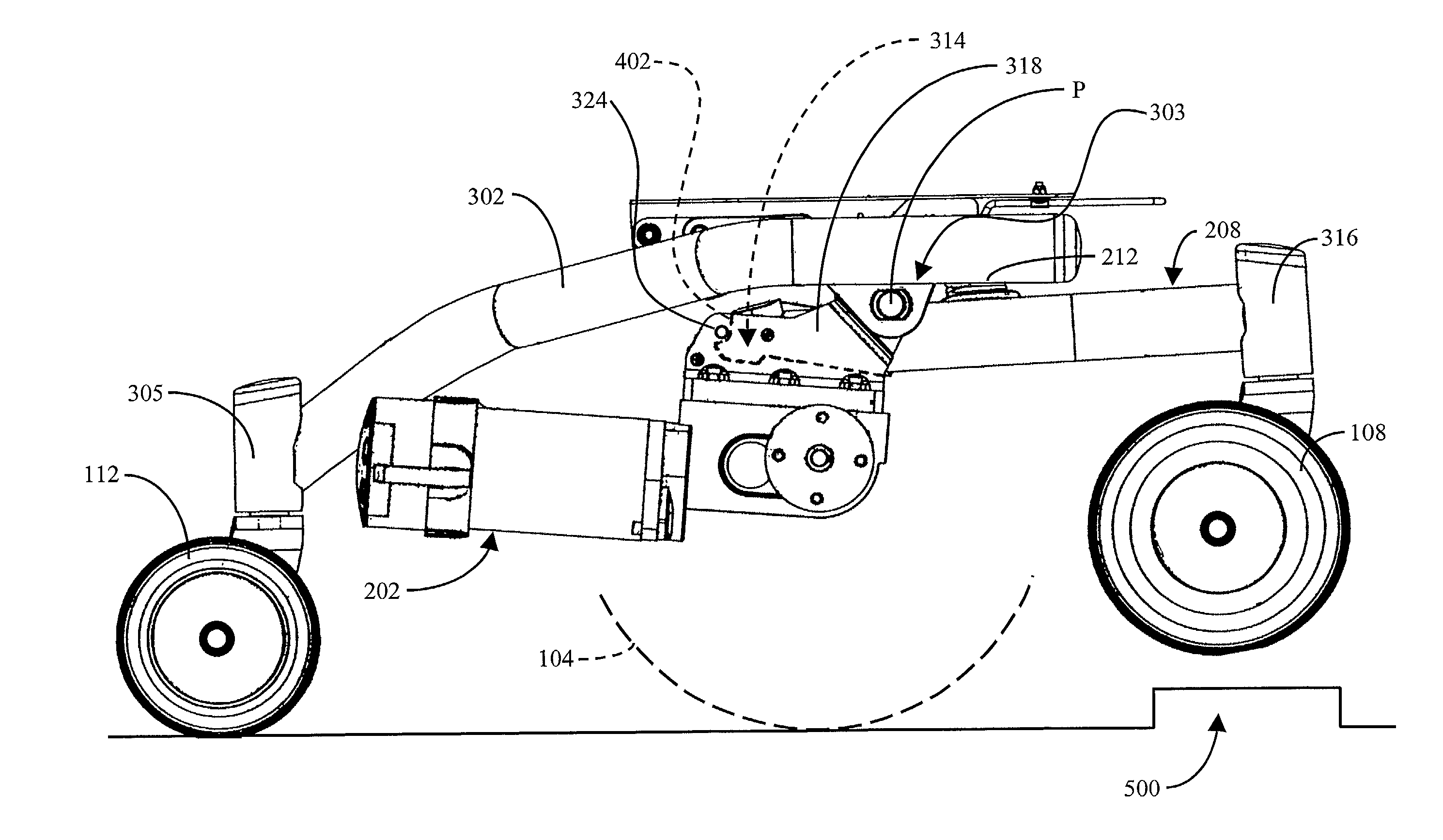
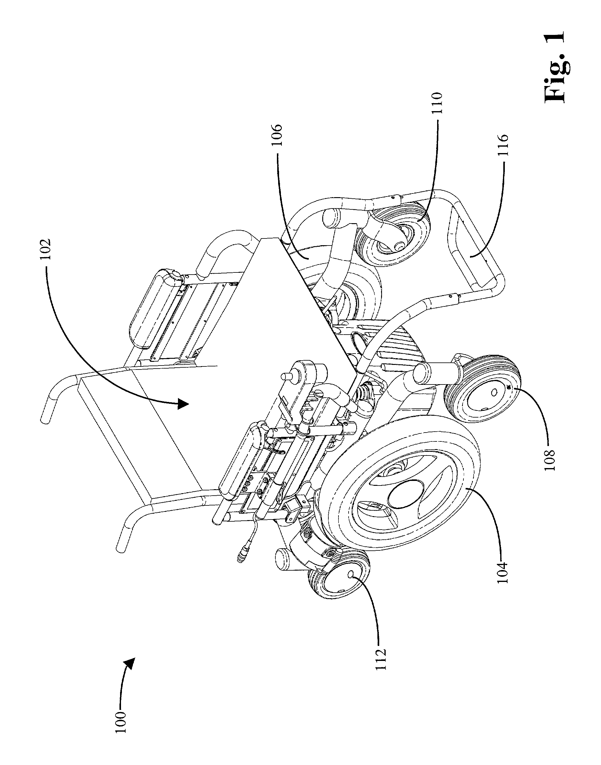
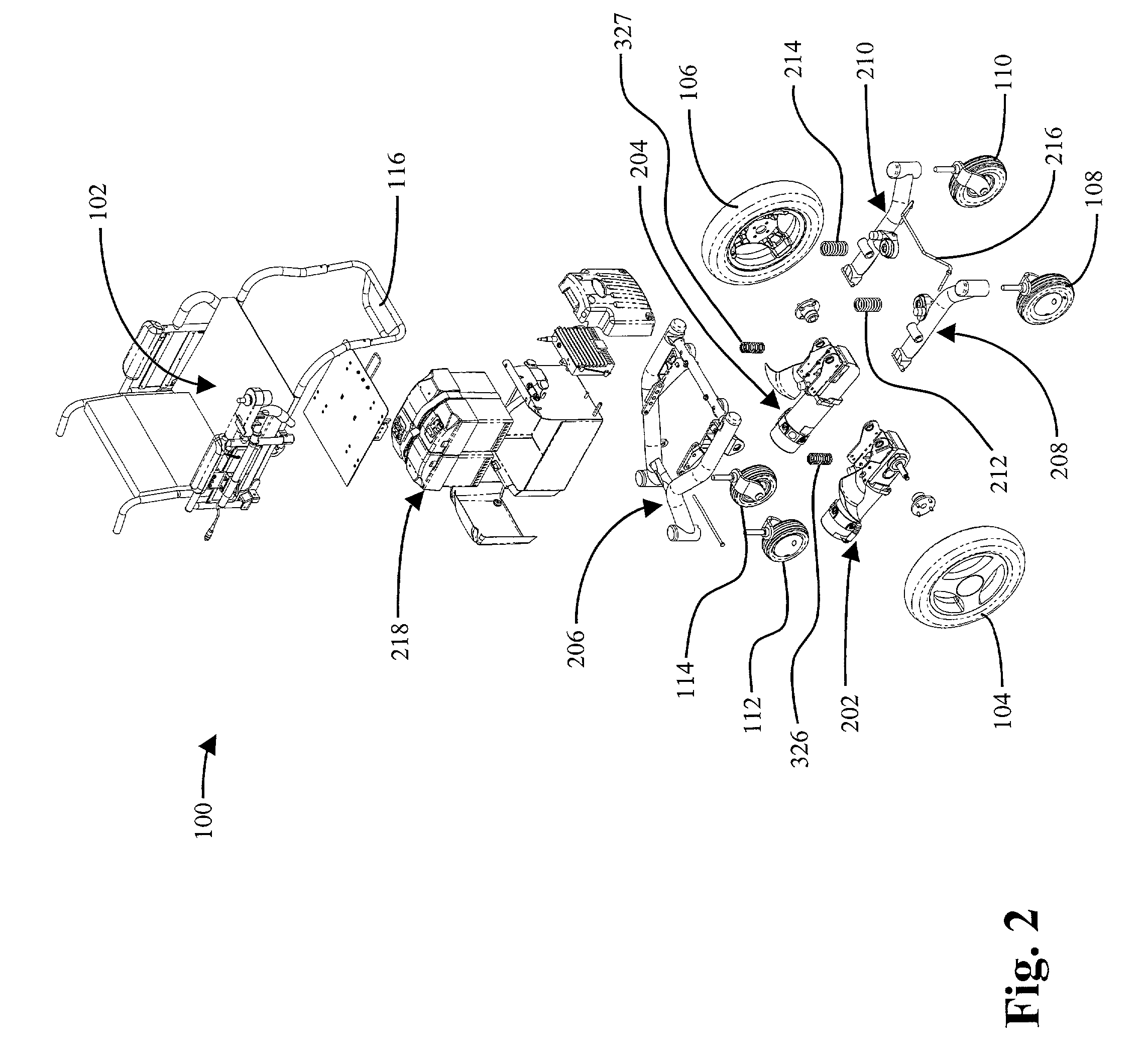
[0019]The present invention provides a suspension system having a pivot arm and a pivoting drive assembly wherein pivotal movement of the drive assembly engages the pivot arm during pivotal motion in one direction and disengages from the pivot arm during pivotal motion in a second direction. When the drive assembly is engaged with the pivot arm, moment arms generated by the drive assembly facilitate upward pivotal movement of the pivot arm to traverse obstacles and rough terrain. In this scenario, the drive assembly and pivot arm pivot act together thereby raising the front castor attached to the pivot arm. Disengagement of the drive assembly from the pivot arm facilitates a smoother ride because the drive assembly can pivot independently of the pivot arm. In this scenario, the drive assembly and pivot arm have independent pivotal motion and function as two separate components.

[0020]Referring now to FIG. 1, a wheelchair 100 of the present invention is shown. Wheelchair 100 has a sea...


PUM


Abstract

The present invention provides a suspension for a conveyance that is capable of traversing obstacles and rough terrain. In this regard, the suspension has a frame member and a pivoting assembly. The pivoting assembly has a pivot arm and a drive assembly. The pivot arm is pivotally coupled to the frame and has a first engagement surface. The drive assembly is pivotally coupled to the frame and has a second engagement surface configured to engage the first engagement surface. The second engagement surface is further configured to disengage from the first engagement surface upon pivotal movement of the drive assembly in a first direction and to re-engage the first engagement surface upon pivotal movement of the drive assembly in a second direction.

Description

FIELD OF THE INVENTION[0001]The invention relates generally to conveyances and, more particularly, to wheelchair suspensions capable of traversing an obstacle or rough terrain.BACKGROUND OF THE INVENTION[0002]Wheelchairs are an important means of transportation for a significant portion of society. Whether manual or powered, wheelchairs provide an important degree of independence for those they assist. However, this degree of independence can be limited if the wheelchair is required to traverse obstacles such as, for example, curbs that are commonly present at sidewalks, driveways, and other paved surface interfaces.[0003]In this regard, most wheelchairs have front and rear casters to stabilize the chair from tipping forward or backward and to ensure that the drive wheels are always in contact with the ground. One such wheelchair is disclosed in U.S. Pat. No. 5,435,404 to Garin. On such wheelchairs, the caster wheels are typically much smaller than the driving wheels and located bot...

Claims


Application Information

Patent Timeline
IPC IPC(8): B60G5/04A61G5/04A61G5/06A61G5/10
CPCA61G5/043A61G5/06Y10S180/907A61G2005/1078A61G5/1078
Inventor FOUGHT, GERALD E.
Owner INVACARE CORP
Learn More